Train Ramp
Note
🌟 Welcome to the SunFounder Facebook Community! Whether you’re into Raspberry Pi, Arduino, or ESP32, you’ll find inspiration, help ideas here.
✅ Be the first to get free learning resources.
✅ Stay updated on new products & exclusive giveaways.
✅ Share your creations and get real feedback.
Kit purchase
Looking for parts? Check out our all-in-one kits below — packed with components, beginner-friendly guides, and tons of fun.

Name |
Includes Arduino board |
PURCHASE LINK |
|---|---|---|
Elite Explorer Kit |
Arduino Uno R4 WiFi |
|
3 in 1 Ultimate Starter Kit |
Arduino Uno R4 Minima |
Course Introduction
In this lesson, you’ll learn how to build an automatic railway crossing using two IR Sensor Modules and two servo motors.
When a train passes the first sensor, the barriers lower to block the road. After the train reaches the second sensor, the barriers rise again, simulating a real railway crossing system.
Note
If this is your first time working with an Arduino project, we recommend downloading and reviewing the basic materials first.
Required Components
In this project, we need the following components:
SN |
COMPONENT INTRODUCTION |
QUANTITY |
PURCHASE LINK |
|---|---|---|---|
1 |
Arduino UNO R4 Minima |
1 |
|
2 |
USB Type-C cable |
1 |
|
3 |
Breadboard |
1 |
|
4 |
Wires |
Several |
|
5 |
Digital Servo Motor |
2 |
|
6 |
IR Obstacle Avoidance Sensor Module |
2 |
Wiring
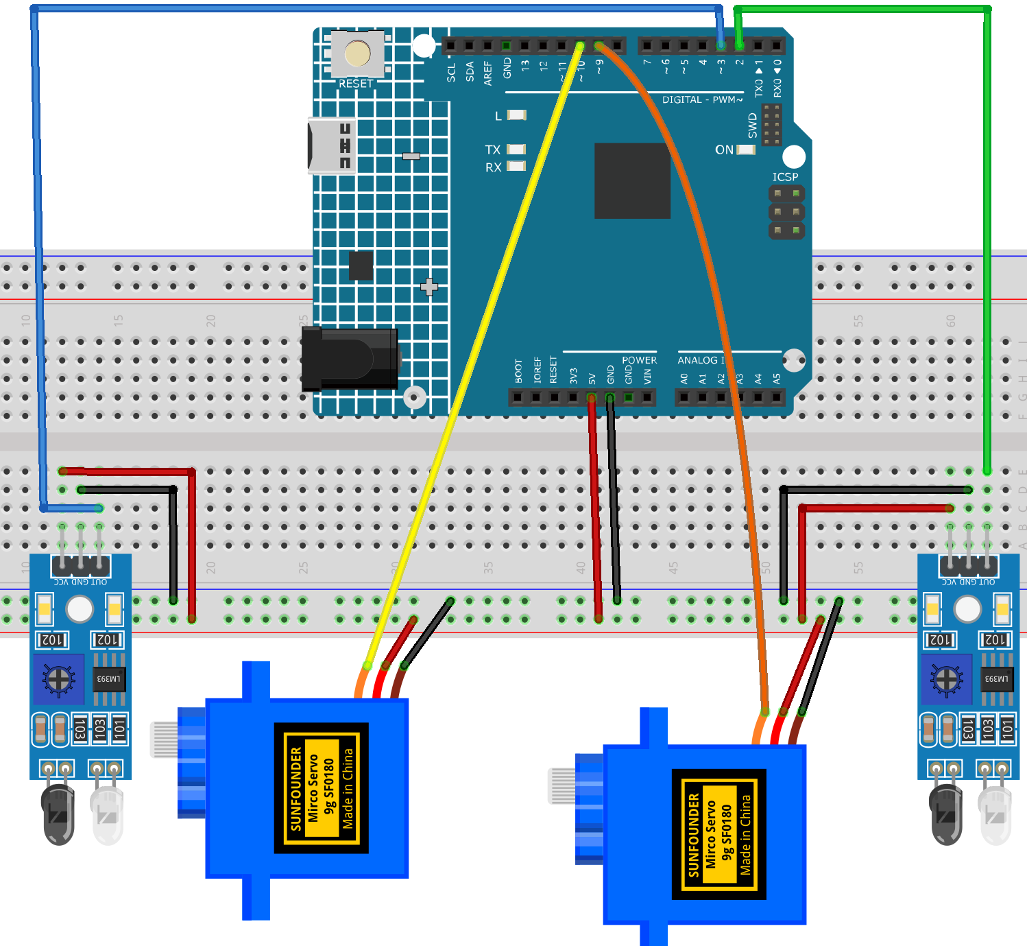
Common Connections:
Digital Servo Motor 1
Connect to breadboard’s positive power bus.
Connect to breadboard’s negative power bus.
Connect to 9 on the Arduino.
Digital Servo Motor 2
Connect to breadboard’s positive power bus.
Connect to breadboard’s negative power bus.
Connect to 10 on the Arduino.
IR Obstacle Avoidance Sensor Module 1
OUT: Connect to 2 on the Arduino.
GND: Connect to breadboard’s negative power bus.
VCC: Connect to breadboard’s red power bus.
IR Obstacle Avoidance Sensor Module 2
OUT: Connect to 3 on the Arduino.
GND: Connect to breadboard’s negative power bus.
VCC: Connect to breadboard’s red power bus.
Writing the Code
Note
You can copy this code into Arduino IDE.
Don’t forget to select the board(Arduino UNO R4 Minima) and the correct port before clicking the Upload button.
#include <Servo.h>

// IR sensor pins
const int IR_ENTRY_PIN = 2;
const int IR_EXIT_PIN = 3;

// Servo pins
const int SERVO_1_PIN = 9;
const int SERVO_2_PIN = 10;

// Servo angles
const int GATE_DOWN_ANGLE = 0;
const int GATE_UP_ANGLE = 90;

// Most IR obstacle sensors output LOW when an object is detected.
// If your sensor works the opposite way, change LOW to HIGH.
const int IR_DETECTED_STATE = LOW;

// Debounce
const unsigned long debounceDelay = 200;

Servo gateServo1;
Servo gateServo2;

bool gateOpen = false;

bool lastEntryState = HIGH;
bool lastExitState = HIGH;

unsigned long lastEntryTime = 0;
unsigned long lastExitTime = 0;

void setup() {
  pinMode(IR_ENTRY_PIN, INPUT);
  pinMode(IR_EXIT_PIN, INPUT);

  gateServo1.attach(SERVO_1_PIN);
  gateServo2.attach(SERVO_2_PIN);

  closeGate();
}

void loop() {
  bool currentEntryState = digitalRead(IR_ENTRY_PIN);
  bool currentExitState = digitalRead(IR_EXIT_PIN);

  unsigned long now = millis();

  // IR Sensor 1 detects the train: raise the barriers
  if (lastEntryState != IR_DETECTED_STATE && currentEntryState == IR_DETECTED_STATE) {
    if (now - lastEntryTime > debounceDelay) {
      openGate();
      lastEntryTime = now;
    }
  }

  // IR Sensor 2 detects the train: lower the barriers
  if (lastExitState != IR_DETECTED_STATE && currentExitState == IR_DETECTED_STATE) {
    if (now - lastExitTime > debounceDelay) {
      closeGate();
      lastExitTime = now;
    }
  }

  lastEntryState = currentEntryState;
  lastExitState = currentExitState;
}

void openGate() {
  gateOpen = true;
  gateServo1.write(GATE_UP_ANGLE);
  gateServo2.write(GATE_UP_ANGLE);
}

void closeGate() {
  gateOpen = false;
  gateServo1.write(GATE_DOWN_ANGLE);
  gateServo2.write(GATE_DOWN_ANGLE);
}