Touch Toggle
Note
🌟 Welcome to the SunFounder Facebook Community! Whether you’re into Raspberry Pi, Arduino, or ESP32, you’ll find inspiration, help ideas here.
✅ Be the first to get free learning resources.
✅ Stay updated on new products & exclusive giveaways.
✅ Share your creations and get real feedback.
Kit purchase
Looking for parts? Check out our all-in-one kits below — packed with components, beginner-friendly guides, and tons of fun.

Name |
Includes Arduino board |
PURCHASE LINK |
|---|---|---|
Ultimate Sensor Kit |
Arduino Uno R4 Minima |
|
Elite Explorer Kit |
Arduino Uno R4 WiFi |
|
3 in 1 Ultimate Starter Kit |
Arduino Uno R4 Minima |
|
Universal Maker Sensor Kit |
× |
Course Introduction
This Arduino project uses a touch sensor and a traffic light LED module to simulate a simple traffic light system. Each time the touch sensor is pressed, the LEDs switch in sequence from red to yellow to green. This example demonstrates how to use a touch sensor as an input trigger to control multiple LEDs in a sequence.
Note
If this is your first time working with an Arduino project, we recommend downloading and reviewing the basic materials first.
Required Components
In this project, we need the following components:
SN |
COMPONENT INTRODUCTION |
QUANTITY |
PURCHASE LINK |
|---|---|---|---|
1 |
Arduino UNO R4 Minima |
1 |
|
2 |
USB Type-C cable |
1 |
|
3 |
Breadboard |
1 |
|
4 |
Wires |
Several |
|
5 |
Touch Sensor Module |
1 |
|
6 |
Traffic Light LED |
1 |
Wiring
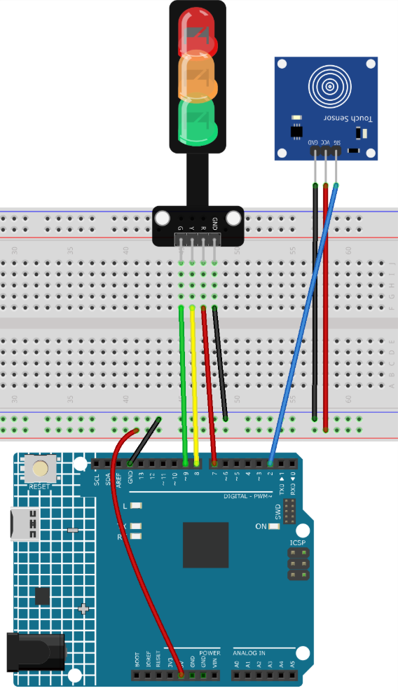
Common Connections:
Traffic light LED
R: Connect to 7 on the Arduino.
Y: Connect to 8 on the Arduino.
G: Connect to 9 on the Arduino.
GND: Connect to GND on the Arduino.
Touch Sensor Module
SIG: Connect to 2 on the Arduino.
GND: Connect to breadboard’s negative power bus.
VCC: Connect to breadboard’s red power bus.
Writing the Code
Note
You can copy this code into Arduino IDE.
Don’t forget to select the board(Arduino UNO R4 Minima/WIFI) and the correct port before clicking the Upload button.
/*
  The code controls a traffic light LED module with a touch sensor.
  Once the touch sensor is activated, the LEDs cycle through turning
  on in sequence: Red -> Yellow -> Green.

  Board: Arduino Uno R4 (or R3)
  Component: Touch Sensor Module and Traffic Light Module
*/

// Define pins for touch sensor and LEDs
const int touchSensorPin = 2;  // touch sensor pin
const int rledPin = 7;         // red LED pin
const int yledPin = 8;         // yellow LED pin
const int gledPin = 9;         // green LED pin

int lastTouchState;     // the previous state of touch sensor
int currentTouchState;  // the current state of touch sensor
int currentLED = 0;     // current LED 0->Red, 1->Yellow, 2->Green

void setup() {
  Serial.begin(9600);              // initialize serial
  pinMode(touchSensorPin, INPUT);  // configure touch sensor pin as input

  // set LED pins as outputs
  pinMode(rledPin, OUTPUT);
  pinMode(yledPin, OUTPUT);
  pinMode(gledPin, OUTPUT);

  currentTouchState = digitalRead(touchSensorPin);
}

void loop() {
  lastTouchState = currentTouchState;               // save the last state
  currentTouchState = digitalRead(touchSensorPin);  // read new state

  // check if the touch sensor was just touched
  if (lastTouchState == LOW && currentTouchState == HIGH) {
    Serial.println("The sensor is touched");

    turnAllLEDsOff();  // Turn off all LEDs

    // switch on the next LED in sequence
    switch (currentLED) {
      case 0:
        digitalWrite(rledPin, HIGH);
        currentLED = 1;
        break;
      case 1:
        digitalWrite(yledPin, HIGH);
        currentLED = 2;
        break;
      case 2:
        digitalWrite(gledPin, HIGH);
        currentLED = 0;
        break;
    }
  }
}

// function to turn off all LEDs
void turnAllLEDsOff() {
  digitalWrite(rledPin, LOW);
  digitalWrite(yledPin, LOW);
  digitalWrite(gledPin, LOW);
}