Servo Control
Note
🌟 Welcome to the SunFounder Facebook Community! Whether you’re into Raspberry Pi, Arduino, or ESP32, you’ll find inspiration, help ideas here.
✅ Be the first to get free learning resources.
✅ Stay updated on new products & exclusive giveaways.
✅ Share your creations and get real feedback.
Kit purchase
Looking for parts? Check out our all-in-one kits below — packed with components, beginner-friendly guides, and tons of fun.

Name |
Includes Arduino board |
PURCHASE LINK |
|---|---|---|
Elite Explorer Kit |
Arduino Uno R4 WiFi |
|
3 in 1 Ultimate Starter Kit |
Arduino Uno R4 Minima |
Course Introduction
This Arduino project uses a potentiometer to control a servo motor. As the potentiometer is turned, its analog value is read and mapped to an angle between 0° and 180°, which adjusts the servo’s position accordingly.
The angle and raw value are displayed via serial monitor, making it a simple and interactive demo of analog input to motor control.
Note
If this is your first time working with an Arduino project, we recommend downloading and reviewing the basic materials first.
Required Components
In this project, we need the following components:
SN |
COMPONENT INTRODUCTION |
QUANTITY |
PURCHASE LINK |
|---|---|---|---|
1 |
Arduino UNO R4 WIFI |
1 |
|
2 |
USB Type-C cable |
1 |
|
3 |
Breadboard |
1 |
|
4 |
Wires |
Several |
|
5 |
Digital Servo Motor |
1 |
|
6 |
Potentiometer Sensor Module |
1 |
Wiring
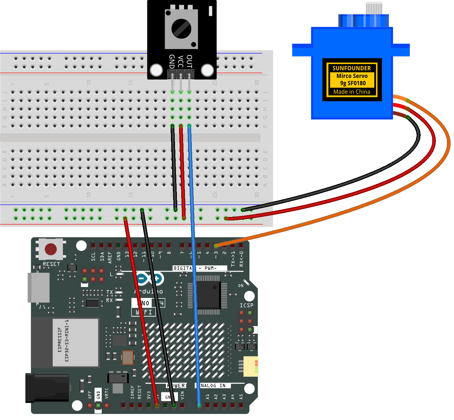
Common Connections:
Digital Servo Motor
Connect to breadboard’s positive power bus.
Connect to breadboard’s negative power bus.
Connect to 3 on the Arduino.
Potentiometer Sensor Module
OUT: Connect to A0 on the Arduino.
GND: Connect to breadboard’s negative power bus.
VCC: Connect to breadboard’s red power bus.
Writing the Code
Note
You can copy this code into Arduino IDE.
Don’t forget to select the board(Arduino UNO R4 Minima/WIFI) and the correct port before clicking the Upload button.
#include <Servo.h>

// Define the potentiometer pin and the servo pin
const int potPin = A0;     // Potentiometer connected to analog pin A0
const int servoPin = 3;    // Servo connected to digital pin 3

// Create a servo object
Servo myServo;

void setup() {
  myServo.attach(servoPin);  // Attach the servo to pin 3
  Serial.begin(9600);        // Start serial communication
}

void loop() {
  int potValue = analogRead(potPin);                // Read analog value (0~1023)
  int angle = map(potValue, 0, 1023, 0, 180);        // Map to servo angle
  myServo.write(angle);                             // Set servo position

  // Debug output
  Serial.print("Potentiometer Value: ");
  Serial.print(potValue);
  Serial.print(" | Servo Angle: ");
  Serial.println(angle);

  delay(15); // Delay to smooth out the signal
}