Parking Lot 2.0
Note
🌟 Welcome to the SunFounder Facebook Community! Whether you’re into Raspberry Pi, Arduino, or ESP32, you’ll find inspiration, help ideas here.
✅ Be the first to get free learning resources.
✅ Stay updated on new products & exclusive giveaways.
✅ Share your creations and get real feedback.
Kit purchase
Looking for parts? Check out our all-in-one kits below — packed with components, beginner-friendly guides, and tons of fun.

Name |
Includes Arduino board |
PURCHASE LINK |
|---|---|---|
Elite Explorer Kit |
Arduino Uno R4 WiFi |
|
3 in 1 Ultimate Starter Kit |
Arduino Uno R4 Minima |
Course Introduction
In this project, you’ll use an Arduino board, an ultrasonic sensor, a servo motor, LEDs, and a buzzer to create a smart parking gate system.
The system automatically opens the gate for incoming vehicles, tracks the number of cars, and uses LEDs and a buzzer to indicate when the lot is full. A reset button allows manual system control for testing or restarting.
Note
If this is your first time working with an Arduino project, we recommend downloading and reviewing the basic materials first.
Required Components
In this project, we need the following components:
SN |
COMPONENT INTRODUCTION |
QUANTITY |
PURCHASE LINK |
|---|---|---|---|
1 |
Arduino UNO R4 Minima/Arduino UNO R4 WIFI |
1 |
|
2 |
USB Type-C cable |
1 |
|
3 |
Breadboard |
1 |
|
4 |
Wires |
Several |
|
5 |
Ultrasonic Sensor Module |
1 |
|
6 |
Digital Servo Motor |
1 |
|
7 |
Active Buzzer |
1 |
|
8 |
LED |
3 |
|
9 |
Button |
1 |
Wiring
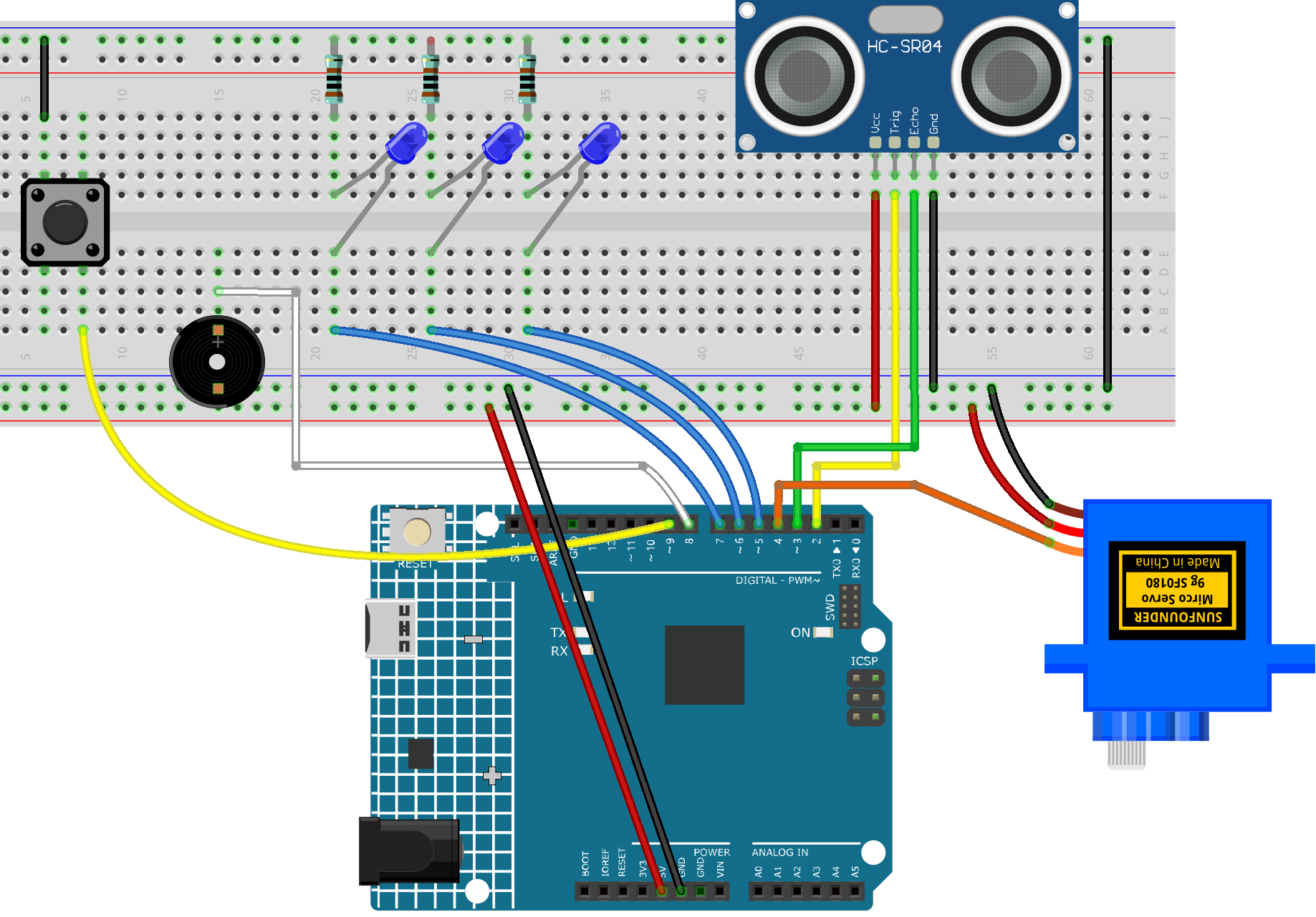
Common Connections:
Button
Connect to breadboard’s negative power bus.
Connect to 9 on the Arduino.
Ultrasonic Sensor Module
Trig: Connect to 2 on the Arduino.
Echo: Connect to 3 on the Arduino.
GND: Connect to breadboard’s negative power bus.
VCC: Connect to breadboard’s red power bus.
Active Buzzer
+: Connect to 8 on the Arduino.
-: Connect to breadboard’s negative power bus.
Digital Servo Motor
Connect to breadboard’s positive power bus.
Connect to breadboard’s negative power bus.
Connect to 4 on the Arduino.
LEDS
Connect the LED anode to 5~7 on the Arduino, and the cathode to a 1kΩ resistor, then to the negative power bus on the breadboard.
Writing the Code
Note
You can copy this code into Arduino IDE.
Don’t forget to select the board(Arduino UNO R4 Minima/WIFI) and the correct port before clicking the Upload button.
#include <Servo.h>

// Pins
#define TRIG_PIN 2
#define ECHO_PIN 3
#define SERVO_PIN 4
#define LED1 5
#define LED2 6
#define LED3 7
#define BUZZER 8
#define BUTTON 9

// Objects
Servo gateServo;

// Variables
int vehicleCount = 0;
bool alertMode = false;
long distance;
unsigned long lastFlashTime = 0;
bool ledState = false;

void setup() {
  Serial.begin(9600);

  pinMode(TRIG_PIN, OUTPUT);
  pinMode(ECHO_PIN, INPUT);

  pinMode(LED1, OUTPUT);
  pinMode(LED2, OUTPUT);
  pinMode(LED3, OUTPUT);
  pinMode(BUZZER, OUTPUT);
  pinMode(BUTTON, INPUT_PULLUP); // Using internal pull-up

  gateServo.attach(SERVO_PIN);
  gateServo.write(0); // Gate down

  // Turn off LEDs and buzzer at start
  digitalWrite(LED1, LOW);
  digitalWrite(LED2, LOW);
  digitalWrite(LED3, LOW);
  digitalWrite(BUZZER, LOW);
}

void loop() {
  distance = getDistance();

  // Button pressed: reset system
  if (digitalRead(BUTTON) == LOW) {
    vehicleCount = 0;
    alertMode = false;
    digitalWrite(BUZZER, LOW);
    digitalWrite(LED1, LOW);
    digitalWrite(LED2, LOW);
    digitalWrite(LED3, LOW);
    Serial.println("System Reset");
    delay(500); // Debounce
  }

  // Vehicle detected within 10 cm range
  if (distance > 0 && distance < 10) {
    handleVehicleDetection();
    delay(1000); // Prevent multiple counts for same vehicle
  }

  // If over capacity and vehicle still there, alert
  if (vehicleCount >= 3 && distance > 0 && distance < 10) {
    alertMode = true;
  } else {
    alertMode = false;
    digitalWrite(BUZZER, LOW);
  }

  if (alertMode) {
    flashLEDs();
    digitalWrite(BUZZER, HIGH);
  }
}

// Function to measure distance from ultrasonic sensor
long getDistance() {
  digitalWrite(TRIG_PIN, LOW);
  delayMicroseconds(2);
  digitalWrite(TRIG_PIN, HIGH);
  delayMicroseconds(10);
  digitalWrite(TRIG_PIN, LOW);

  long duration = pulseIn(ECHO_PIN, HIGH, 30000); // Timeout 30ms
  if (duration == 0) return -1; // Timeout
  return duration * 0.034 / 2;
}

// Vehicle enters: open gate, count, close
void handleVehicleDetection() {
  if (vehicleCount < 3) {
    vehicleCount++;
    Serial.print("Vehicle Count: ");
    Serial.println(vehicleCount);
    updateLEDs();

    gateServo.write(90); // Gate up
    delay(3000);
    gateServo.write(0); // Gate down
  }
}

// Update LEDs based on vehicle count
void updateLEDs() {
  digitalWrite(LED1, vehicleCount >= 1 ? HIGH : LOW);
  digitalWrite(LED2, vehicleCount >= 2 ? HIGH : LOW);
  digitalWrite(LED3, vehicleCount >= 3 ? HIGH : LOW);
}

// Flash LEDs in alert mode
void flashLEDs() {
  unsigned long now = millis();
  if (now - lastFlashTime >= 500) {
    ledState = !ledState;
    digitalWrite(LED1, ledState);
    digitalWrite(LED2, ledState);
    digitalWrite(LED3, ledState);
    lastFlashTime = now;
  }
}