Light Sensing
Note
🌟 Welcome to the SunFounder Facebook Community! Whether you’re into Raspberry Pi, Arduino, or ESP32, you’ll find inspiration, help ideas here.
✅ Be the first to get free learning resources.
✅ Stay updated on new products & exclusive giveaways.
✅ Share your creations and get real feedback.
👉 Need faster updates or support? Click [here] join our Facebook community
👉 Or join our WhatsApp group: Click [here]
🎁 Looking for parts?Check out our all-in-one kits below — packed with components, beginner-friendly guides, and tons of fun.
Name |
Includes Arduino board |
PURCHASE LINK |
|---|---|---|
Ultimate Sensor Kit |
Arduino Uno R4 Minima |
|
Elite Explorer Kit |
Arduino Uno R4 WiFi |
|
3 in 1 Ultimate Starter Kit |
Arduino Uno R4 Minima |
Course Introduction
In this lesson, you’ll build a light detection system using an Arduino UNO R4, an LDR, and a TM1637 display.
The display shows a 0–100 value that increases with light intensity, allowing real-time brightness monitoring.
Note
If this is your first time working with an Arduino project, we recommend downloading and reviewing the basic materials first.
Required Components
In this project, we need the following components:
SN |
COMPONENT INTRODUCTION |
QUANTITY |
PURCHASE LINK |
|---|---|---|---|
1 |
Arduino UNO R4 Minima/Arduino UNO R4 WIFI |
1 |
|
2 |
USB Type-C cable |
1 |
|
3 |
Breadboard |
1 |
|
4 |
Wires |
Several |
|
5 |
4-Digit Segment Display Module |
1 |
|
6 |
Photoresistor |
1 |
|
7 |
10kΩ resistor |
1 |
Wiring
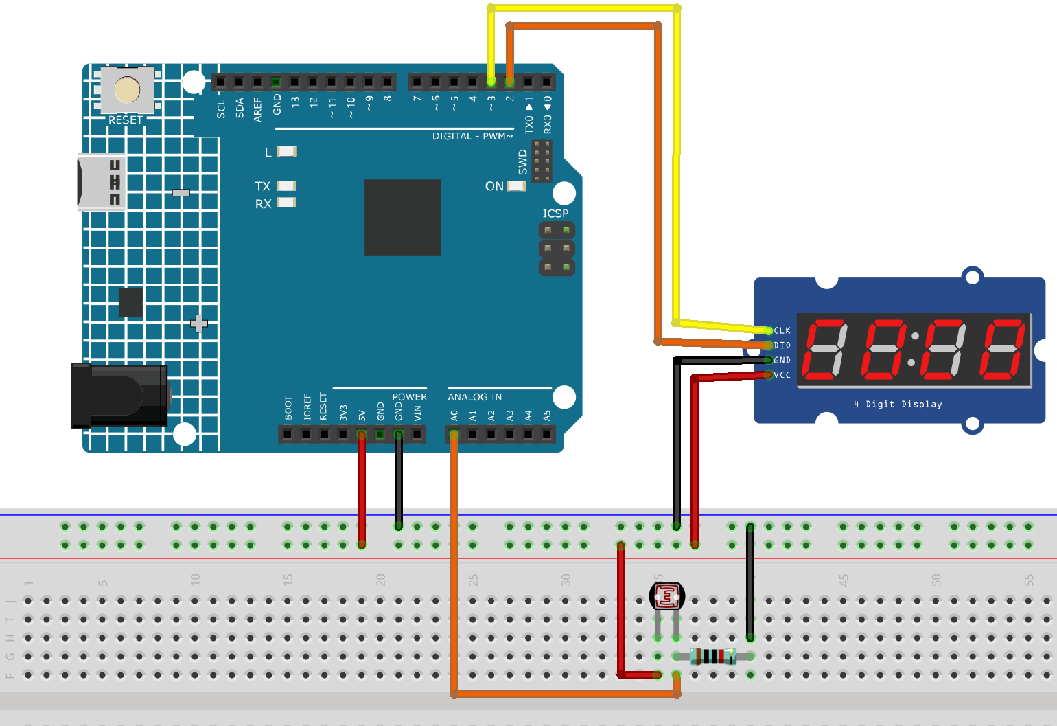
Common Connections:
Photoresistor
Connect to A0 on the Arduino. Then connect a 10k resistor to the negative power bus of the breadboard
Connect to breadboard’s red power bus.
4-Digit Segment Display Module
CLK: Connect to 3 on the Arduino.
DIO: Connect to 2 on the Arduino.
GND: Connect to breadboard’s negative power bus.
VCC: Connect to breadboard’s red power bus.
Writing the Code
Note
You can copy this code into Arduino IDE.
To install the library, use the Arduino Library Manager and search for TM1637Display and install it.
Don’t forget to select the board(Arduino UNO R4 Minima/WIFI) and the correct port before clicking the Upload button.
#include <TM1637Display.h>

// -------- TM1637 pins (UNO R4) --------
#define CLK_PIN 3     // TM1637 CLK
#define DIO_PIN 2     // TM1637 DIO
TM1637Display display(CLK_PIN, DIO_PIN);

// -------- LDR analog pin --------
const int LDR_PIN = A0;

// -------- timing --------
const unsigned long SAMPLE_MS = 50;    // sample period
const unsigned long CALIB_MS  = 3000;  // auto-calibration duration

// auto-calibration range (updated during first CALIB_MS)
int adcMinSeen = 1023;
int adcMaxSeen = 0;

// simple low-pass filter (EMA)
float ema = 0.0f;
const float ALPHA = 0.25f; // 0~1, higher = more responsive

unsigned long t0;

void setup() {
  display.setBrightness(7);
  display.clear();

  // UNO R4 analogRead default is 0~1023 (10-bit), keep default
  // For higher resolution, you can enable: analogReadResolution(12); // 0~4095

  // Show "CAL " during calibration
  display.showNumberDecEx(0, 0, true, 4, 0); // clear
  display.setSegments((const uint8_t[]){0x39, 0x77, 0x38, 0x00}); // display "CAL "
  // If your library version doesn't support this, you can comment these two lines

  t0 = millis();
}

void loop() {
  static unsigned long last = 0;
  unsigned long now = millis();
  if (now - last < SAMPLE_MS) return;
  last = now;

  int adc = analogRead(LDR_PIN);   // 0(dark)~1023(bright) or reversed depending on wiring

  // 1) Auto-calibration during the first 3 seconds
  if (now - t0 < CALIB_MS) {
    if (adc < adcMinSeen) adcMinSeen = adc;
    if (adc > adcMaxSeen) adcMaxSeen = adc;
    return; // During calibration, do not update display
  }

  // If calibration range is too narrow, set default values
  if (adcMaxSeen - adcMinSeen < 50) {
    adcMinSeen = 100;
    adcMaxSeen = 900;
  }

  // 2) Map ADC to 0~100 (based on calibration range)
  // Regardless of wiring direction, map so that brighter = larger value
  int span = adcMaxSeen - adcMinSeen;
  long mapped = (long)(adc - adcMinSeen) * 100 / (span <= 0 ? 1 : span);
  if (mapped < 0)   mapped = 0;
  if (mapped > 100) mapped = 100;

  // 3) EMA smoothing
  ema = (1.0f - ALPHA) * ema + ALPHA * mapped;
  int value = (int)(ema + 0.5f);

  // 4) Display on TM1637 (0~100)
  // Right aligned: e.g. “  85”, “ 100”
  display.showNumberDec(value, true, 3, 1); // use last 3 digits for better centering
  // If you want right alignment using all 4 digits: display.showNumberDec(value, true);

  // (Optional) Update min/max boundaries slowly over time to adapt to environment:
  // if (value < 5)  adcMinSeen = (adcMinSeen*3 + adc)/4;
  // if (value > 95) adcMaxSeen = (adcMaxSeen*3 + adc)/4;
}