Touch Pet
Note
🌟 Welcome to the SunFounder Facebook Community! Whether you’re into Raspberry Pi, Arduino, or ESP32, you’ll find inspiration, help ideas here.
✅ Be the first to get free learning resources.
✅ Stay updated on new products & exclusive giveaways.
✅ Share your creations and get real feedback.
Kit purchase
Looking for parts? Check out our all-in-one kits below — packed with components, beginner-friendly guides, and tons of fun.
Name |
Includes Arduino board |
PURCHASE LINK |
|---|---|---|
Elite Explorer Kit |
Arduino Uno R4 WiFi |
|
Inventor Lab Kit |
Arduino Uno R3 |
Course Introduction
In this lesson, you’ll learn how to use an OLED display, a touch sensor, and a passive buzzer with the Arduino R4 UNO to create a touch-interactive digital pet.
The OLED shows a cute pet face in its normal state. When the touch sensor is triggered, the pet randomly changes to different emotions, such as love, happy, relaxed, or excited, while the buzzer plays a short sound effect.
Note
If this is your first time working with an Arduino project, we recommend downloading and reviewing the basic materials first.
Required Components
In this project, we need the following components:
SN |
COMPONENT INTRODUCTION |
QUANTITY |
PURCHASE LINK |
|---|---|---|---|
1 |
Arduino UNO R4 Minima |
1 |
|
2 |
USB Type-C cable |
1 |
|
3 |
Breadboard |
1 |
|
4 |
Wires |
Several |
|
5 |
Button |
3 |
|
6 |
OLED Display Module |
1 |
|
7 |
Passive Buzzer |
1 |
|
8 |
Touch Sensor Module |
1 |
Wiring
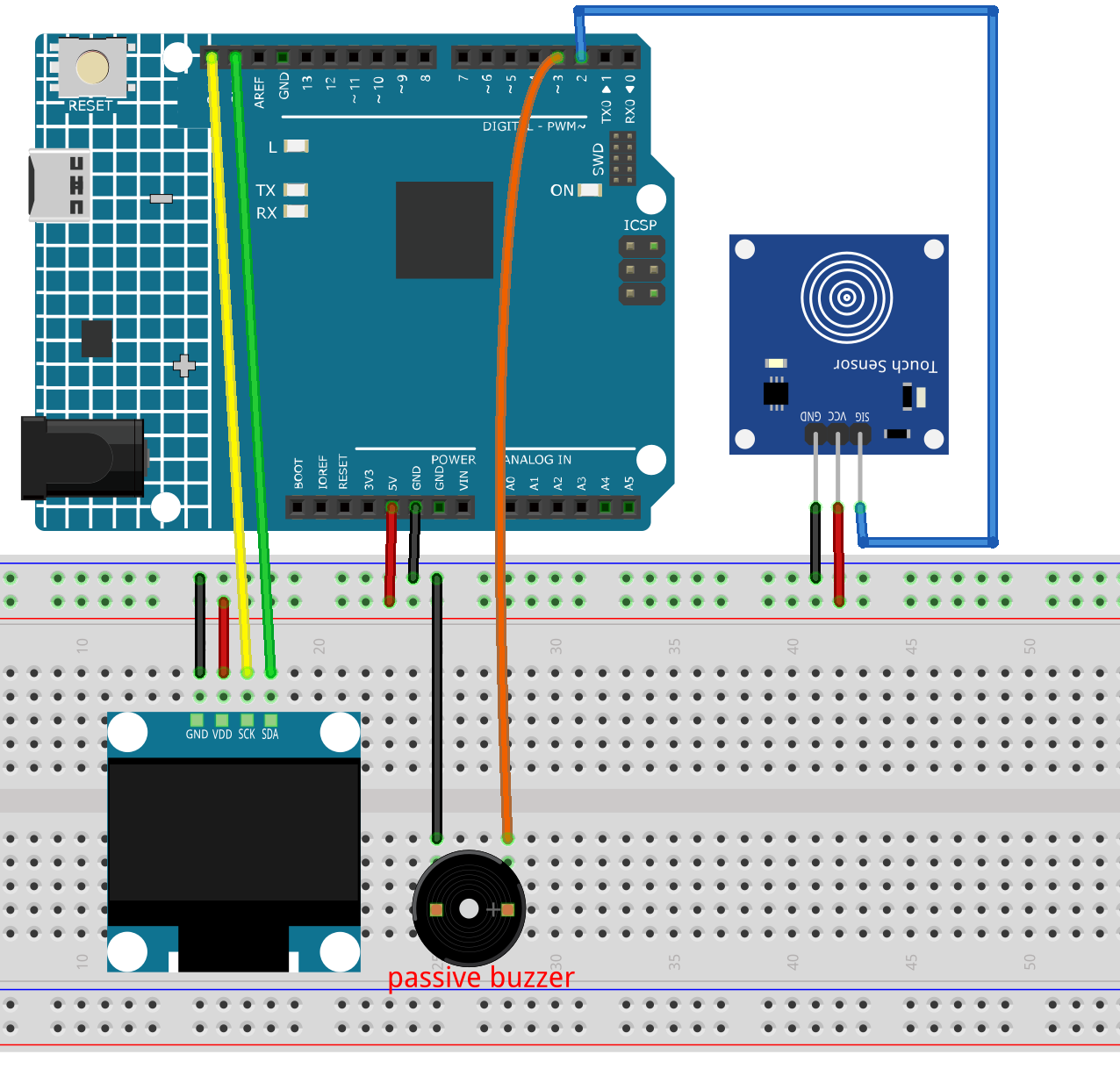
Common Connections:
OLED Display Module
SDA: Connect to SDA on the Arduino.
SCK: Connect to SCL on the Arduino.
GND: Connect to breadboard’s negative power bus.
VCC: Connect to breadboard’s red power bus.
Passive Buzzer
+: Connect to 3 on the Arduino.
-: Connect to breadboard’s negative power bus.
Touch Sensor Module
SIG: Connect to 2 on the Arduino.
GND: Connect to breadboard’s negative power bus.
VCC: Connect to breadboard’s red power bus.
Writing the Code
Note
You can copy this code into Arduino IDE.
To install the library, use the Arduino Library Manager and search for Adafruit SSD1306 and Adafruit GFX and install it.
Don’t forget to select the board(Arduino UNO R4) and the correct port before clicking the Upload button.
#include <Wire.h>
#include <Adafruit_GFX.h>
#include <Adafruit_SSD1306.h>
#include <Adafruit_NeoPixel.h>

// OLED
#define SCREEN_WIDTH 128
#define SCREEN_HEIGHT 64
#define OLED_RESET -1
#define OLED_ADDR 0x3C

Adafruit_SSD1306 display(SCREEN_WIDTH, SCREEN_HEIGHT, &Wire, OLED_RESET);

// Pins
const int TRIG_PIN = 9;
const int ECHO_PIN = 10;
const int BUZZER_PIN = 5;
const int LED_PIN = 6;

// LED strip
const int LED_COUNT = 8;
Adafruit_NeoPixel strip(LED_COUNT, LED_PIN, NEO_GRB + NEO_KHZ800);

// Distance settings
const int SAFE_DISTANCE_CM = 20;
const int LED_START_CM = 15;
const int DANGER_DISTANCE_CM = 3;

// Buzzer timing
unsigned long lastBeepTime = 0;
bool buzzerState = false;

// Passive buzzer frequency
const int BUZZER_FREQ = 2000;

void setup() {
  pinMode(TRIG_PIN, OUTPUT);
  pinMode(ECHO_PIN, INPUT);
  pinMode(BUZZER_PIN, OUTPUT);

  noTone(BUZZER_PIN);

  strip.begin();
  strip.show();

  if (!display.begin(SSD1306_SWITCHCAPVCC, OLED_ADDR)) {
    while (true);
  }

  display.clearDisplay();
  display.display();
}

void loop() {
  float distanceCM = readDistanceCM();
  int distanceMM = distanceCM * 10;

  updateOLED(distanceMM, distanceCM);
  updateLEDStrip(distanceCM);
  updateBuzzer(distanceCM);

  delay(50);
}

float readDistanceCM() {
  digitalWrite(TRIG_PIN, LOW);
  delayMicroseconds(2);

  digitalWrite(TRIG_PIN, HIGH);
  delayMicroseconds(10);
  digitalWrite(TRIG_PIN, LOW);

  long duration = pulseIn(ECHO_PIN, HIGH, 30000);

  if (duration == 0) {
    return 999;
  }

  return duration * 0.0343 / 2.0;
}

void updateOLED(int distanceMM, float distanceCM) {
  display.clearDisplay();

  display.setTextColor(SSD1306_WHITE);

  display.setTextSize(1);
  display.setCursor(0, 0);
  display.print("Reverse Radar");

  display.setTextSize(2);
  display.setCursor(0, 22);

  if (distanceCM > SAFE_DISTANCE_CM) {
    display.print("SAFE");
  } else {
    display.print(distanceMM);
    display.print("mm");
  }

  display.display();
}

void updateLEDStrip(float distanceCM) {
  if (distanceCM > SAFE_DISTANCE_CM) {
    clearLEDs();
    return;
  }

  if (distanceCM > LED_START_CM) {
    clearLEDs();
    return;
  }

  int ledsOn = 0;

  if (distanceCM <= 0) {
    ledsOn = 1;
  } else {
    ledsOn = ceil(distanceCM / 2.0);
  }

  ledsOn = constrain(ledsOn, 1, LED_COUNT);

  uint32_t color;

  if (distanceCM >= 9 && distanceCM <= 15) {
    color = strip.Color(0, 255, 0);       // Green
  } else if (distanceCM > 5 && distanceCM < 9) {
    color = strip.Color(255, 180, 0);     // Yellow
  } else {
    color = strip.Color(255, 0, 0);       // Red
  }

  clearLEDs();

  for (int i = 0; i < ledsOn; i++) {
    strip.setPixelColor(i, color);
  }

  strip.show();
}

void updateBuzzer(float distanceCM) {
  if (distanceCM > SAFE_DISTANCE_CM) {
    noTone(BUZZER_PIN);
    buzzerState = false;
    return;
  }

  if (distanceCM < DANGER_DISTANCE_CM) {
    tone(BUZZER_PIN, BUZZER_FREQ);  // Long beep
    return;
  }

  int beepInterval = map(distanceCM, 3, 20, 100, 800);
  beepInterval = constrain(beepInterval, 100, 800);

  if (millis() - lastBeepTime >= beepInterval) {
    lastBeepTime = millis();

    buzzerState = !buzzerState;

    if (buzzerState) {
      tone(BUZZER_PIN, BUZZER_FREQ);
    } else {
      noTone(BUZZER_PIN);
    }
  }
}

void clearLEDs() {
  for (int i = 0; i < LED_COUNT; i++) {
    strip.setPixelColor(i, 0, 0, 0);
  }
  strip.show();
}