Radar Guard 10.0
Note
🌟 Welcome to the SunFounder Facebook Community! Whether you’re into Raspberry Pi, Arduino, or ESP32, you’ll find inspiration, help ideas here.
✅ Be the first to get free learning resources.
✅ Stay updated on new products & exclusive giveaways.
✅ Share your creations and get real feedback.
Kit purchase
Looking for parts? Check out our all-in-one kits below — packed with components, beginner-friendly guides, and tons of fun.

Name |
Includes Arduino board |
PURCHASE LINK |
|---|---|---|
Ultimate Sensor Kit |
Arduino Uno R4 Minima |
|
Elite Explorer Kit |
Arduino Uno R4 WiFi |
|
3 in 1 Ultimate Starter Kit |
Arduino Uno R4 Minima |
|
Universal Maker Sensor Kit |
× |
Course Introduction
In this lesson, you’ll build an ultrasonic safety scanner using a servo, LEDs, and a buzzer. The servo sweeps the ultrasonic sensor to detect distance, while the LEDs change from green to yellow to red based on how close an object is. In danger zones, the buzzer sounds an alert with different beeping patterns.
Note
If this is your first time working with an Arduino project, we recommend downloading and reviewing the basic materials first.
Required Components
In this project, we need the following components:
SN |
COMPONENT INTRODUCTION |
QUANTITY |
PURCHASE LINK |
|---|---|---|---|
1 |
Arduino UNO R4 Minima/Arduino UNO R4 WIFI |
1 |
|
2 |
USB Type-C cable |
1 |
|
3 |
Breadboard |
1 |
|
4 |
Wires |
Several |
|
5 |
Ultrasonic Sensor Module |
1 |
|
6 |
I2C LCD 1602 |
1 |
|
7 |
Digital Servo Motor |
1 |
|
8 |
Buzzer Module |
1 |
|
9 |
Traffic Light LED |
1 |
Wiring
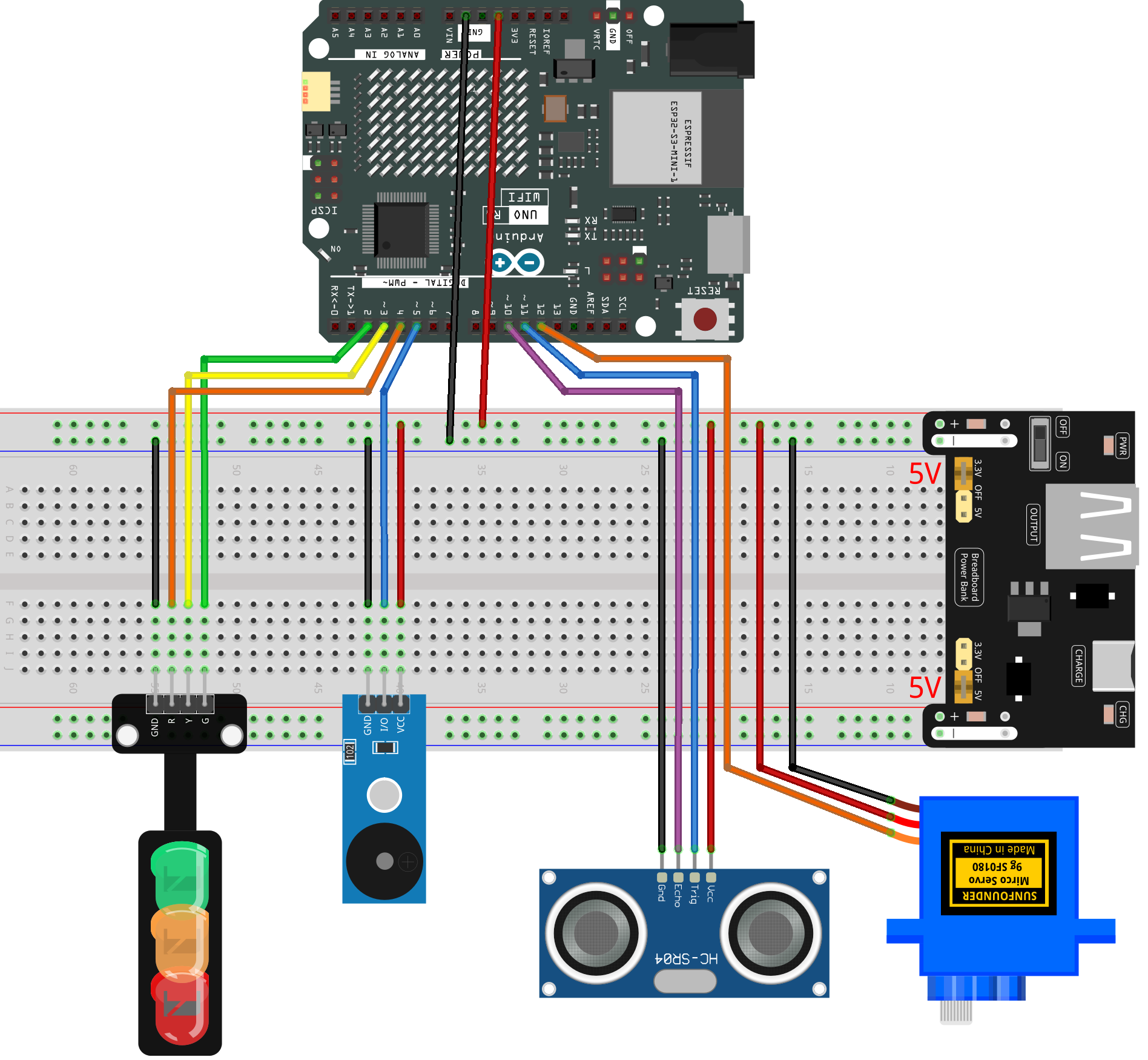
Common Connections:
Traffic light LED
R: Connect to 2 on the Arduino.
Y: Connect to 3 on the Arduino.
G: Connect to 4 on the Arduino.
GND: Connect to GND on the Arduino.
Digital Servo Motor
Connect to breadboard’s positive power bus.
Connect to breadboard’s negative power bus.
Connect to 12 on the Arduino.
Buzzer Modudle
I/O: Connect to 5 on the Arduino.
GND: Connect to breadboard’s negative power bus.
VCC: Connect to breadboard’s red power bus.
Ultrasonic Sensor Module
Trig: Connect to 11 on the Arduino.
Echo: Connect to 10 on the Arduino.
GND: Connect to breadboard’s negative power bus.
VCC: Connect to breadboard’s red power bus.
Writing the Code
Note
Build the circuit.
Upload the code to the Arduino board using Arduino IDE.
In the Arduino IDE, check the current Arduino port(COMx).
The
ArduinoRadarGUIis used here. You can click hereRadar_Guard10.0.zipto download it.Open ArduinoLidarGUI.pde in the Processing IDE .
Modify the code in line 35 to ensure the correct port number(COMx).
Run the Processing sketch to visualize the radar data.
#include <Servo.h>

// ------------ Pin Definitions ------------
const int trigPin   = 11;    // Ultrasonic Trig pin
const int echoPin   = 10;    // Ultrasonic Echo pin
const int servoPin  = 12;    // Servo signal pin
const int buzzerPin = 5;     // Passive buzzer
const int greenLED  = 2;     // Traffic light - Green
const int yellowLED = 3;     // Traffic light - Yellow
const int redLED    = 4;     // Traffic light - Red

// ------------ Servo Settings ------------
const int minAngle  = 0;     // Servo minimum angle
const int maxAngle  = 180;   // Servo maximum angle
const int stepAngle = 1;     // Servo movement step
int currentAngle    = minAngle;
int direction       = 1;     // +1 for forward, -1 for backward

// ------------ Distance Thresholds ------------
const int thresholdYellowCM = 30;  // ≤30cm = Yellow zone
const int thresholdRedCM    = 15;  // ≤15cm = Red zone

// ------------ Buzzer Control ------------
bool buzzerEnabled = false;
unsigned long nextBuzzTime = 0;
int buzzerFreq = 2000;     // Default beep frequency
int buzzOnMs    = 80;
int buzzOffMs   = 200;
bool buzzing = false;

// ------------ Timing ------------
unsigned long nextServoMove = 0;
const uint16_t servoStepInterval = 20;

// ------------ Servo Object ------------
Servo scanner;


// ------------ Measure distance (cm) ------------
long measureDistanceCM() {
  digitalWrite(trigPin, LOW);
  delayMicroseconds(2);
  digitalWrite(trigPin, HIGH);
  delayMicroseconds(10);
  digitalWrite(trigPin, LOW);

  unsigned long duration = pulseIn(echoPin, HIGH, 20000); // timeout 20ms
  if (duration == 0) return 9999;                         // No echo

  long distance = duration / 58.0;
  if (distance <= 0) distance = 9999;
  return distance;
}


// ------------ Update LEDs + Buzzer by distance ------------
void updateStateByDistance(long dist) {

  // ---- Red zone ----
  if (dist <= thresholdRedCM) {

    digitalWrite(redLED, HIGH);
    digitalWrite(yellowLED, LOW);
    digitalWrite(greenLED, LOW);

    buzzerEnabled = true;
    buzzerFreq = 2800;   // Danger tone
    buzzOnMs  = 120;
    buzzOffMs = 120;
  }

  // ---- Yellow zone ----
  else if (dist <= thresholdYellowCM) {

    digitalWrite(redLED, LOW);
    digitalWrite(yellowLED, HIGH);
    digitalWrite(greenLED, LOW);

    buzzerEnabled = true;
    buzzerFreq = 2000;   // Warning tone
    buzzOnMs  = 80;
    buzzOffMs = 250;
  }

  // ---- Green zone ----
  else {

    digitalWrite(redLED, LOW);
    digitalWrite(yellowLED, LOW);
    digitalWrite(greenLED, HIGH);

    buzzerEnabled = false;
    noTone(buzzerPin);
  }
}


// ------------ Non-blocking buzzer scheduler ------------
void updateBuzzer(unsigned long now) {
  if (!buzzerEnabled) {
    buzzing = false;
    noTone(buzzerPin);
    return;
  }

  if (now >= nextBuzzTime) {
    if (!buzzing) {
      tone(buzzerPin, buzzerFreq);
      buzzing = true;
      nextBuzzTime = now + buzzOnMs;
    } else {
      noTone(buzzerPin);
      buzzing = false;
      nextBuzzTime = now + buzzOffMs;
    }
  }
}


// ------------ Setup ------------
void setup() {
  Serial.begin(9600);

  pinMode(trigPin, OUTPUT);
  pinMode(echoPin, INPUT);

  pinMode(buzzerPin, OUTPUT);
  pinMode(greenLED, OUTPUT);
  pinMode(yellowLED, OUTPUT);
  pinMode(redLED, OUTPUT);

  // Initial LED state
  digitalWrite(greenLED, HIGH);
  digitalWrite(yellowLED, LOW);
  digitalWrite(redLED, LOW);

  // Servo init
  scanner.attach(servoPin);
  scanner.write(currentAngle);

  nextServoMove = millis();
  nextBuzzTime = millis();
}


// ------------ Main Loop ------------
void loop() {
  unsigned long now = millis();

  // ------ Servo movement control ------
  if (now >= nextServoMove) {
    nextServoMove = now + servoStepInterval;

    currentAngle += direction * stepAngle;

    if (currentAngle >= maxAngle) {
      currentAngle = maxAngle;
      direction = -1;
    }
    else if (currentAngle <= minAngle) {
      currentAngle = minAngle;
      direction = 1;
    }

    scanner.write(currentAngle);

    long dist = measureDistanceCM();

    updateStateByDistance(dist);

    // Send angle + distance to Processing GUI
    Serial.print(currentAngle);
    Serial.print(",");
    Serial.print(dist);
    Serial.print(".");
  }

  // ------ Update buzzer (non-blocking) ------
  updateBuzzer(now);
}