Tilt LED 3.0
Note
🌟 Welcome to the SunFounder Facebook Community! Whether you’re into Raspberry Pi, Arduino, or ESP32, you’ll find inspiration, help ideas here.
✅ Be the first to get free learning resources.
✅ Stay updated on new products & exclusive giveaways.
✅ Share your creations and get real feedback.
Kit purchase
Looking for parts? Check out our all-in-one kits below — packed with components, beginner-friendly guides, and tons of fun.

Name |
Includes Arduino board |
PURCHASE LINK |
|---|---|---|
Elite Explorer Kit |
Arduino Uno R4 WiFi |
|
3 in 1 Ultimate Starter Kit |
Arduino Uno R4 Minima |
Course Introduction
This Arduino project uses an MPU6050 sensor to control two arrays of LEDs, showing the board’s tilt direction and angle in real time.
Red LEDs light up as the board tilts left, while blue LEDs light up as it tilts right. The tilt angle is calculated from accelerometer data, and LEDs activate step by step for every ~7° beyond a small dead zone near 0°.
This creates a clear visual indicator of orientation, with live angle values also printed to the serial monitor.
Note
If this is your first time working with an Arduino project, we recommend downloading and reviewing the basic materials first.
Required Components
In this project, we need the following components:
SN |
COMPONENT INTRODUCTION |
QUANTITY |
PURCHASE LINK |
|---|---|---|---|
1 |
Arduino UNO R4 |
1 |
|
2 |
USB Type-C cable |
1 |
|
3 |
Breadboard |
1 |
|
4 |
Wires |
Several |
|
5 |
1kΩ resistor |
Several |
|
12 |
LED |
Several |
|
7 |
MPU6050 Module |
1 |
Wiring
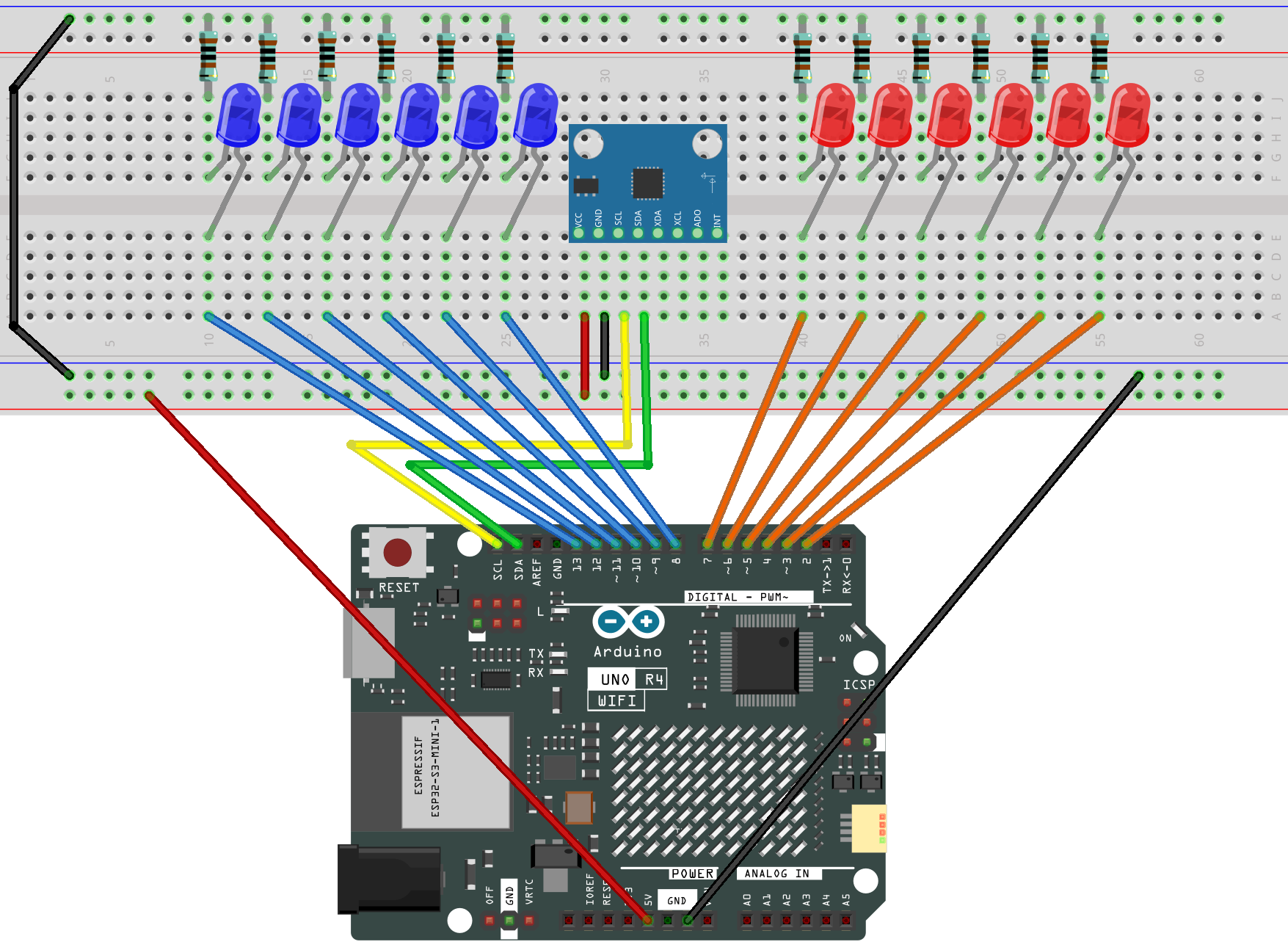
Common Connections:
BLUE LED
Connect the LEDs cathode to a 1kΩ resistor then to the negative power bus on the breadboard, and the LEDs anode to 2 to 7 on the Arduino.
RED LED
Connect the LEDs cathode to a 1kΩ resistor then to the negative power bus on the breadboard, and the LEDs anode to 8 to 13 on the Arduino.
MPU6050
SDA: Connect to SDA on the Arduino.
SCL: Connect to SCL on the Arduino.
GND: Connect to breadboard’s negative power bus.
VCC: Connect to breadboard’s red power bus.
Writing the Code
Note
You can copy this code into Arduino IDE.
To install the library, use the Arduino Library Manager and search for MPU6050 and install it.
Don’t forget to select the board(Arduino UNO R3) and the correct port before clicking the Upload button.
#include <Wire.h>
#include <MPU6050.h>

MPU6050 mpu;

// Red LEDs on pins 7-2 (reverse order, from center to left edge)
const int redPins[] = {7, 6, 5, 4, 3, 2};
const int redCount = sizeof(redPins) / sizeof(redPins[0]);

// Blue LEDs on pins 8-13 (from center to right edge)
const int bluePins[] = {8, 9, 10, 11, 12, 13};
const int blueCount = sizeof(bluePins) / sizeof(bluePins[0]);

// Dead zone around 0° (avoid flicker when board is almost flat)
const float deadZone = 5.0;

// Angle step per LED (each LED lights up per 7° tilt)
const float anglePerLED = 7.0;

void setup() {
  Serial.begin(9600); // Start serial monitor for debugging

  Wire.begin();            // Start I2C communication
  Wire.setClock(100000);   // Set I2C speed to 100kHz (more stable)

  // Initialize MPU6050 sensor
  mpu.initialize();
  if (!mpu.testConnection()) {
    Serial.println("MPU6050 connection failed at startup!");
    while (1); // Stop here if MPU6050 not connected
  }

  // Initialize red LEDs as outputs
  for (int i = 0; i < redCount; i++) {
    pinMode(redPins[i], OUTPUT);
    digitalWrite(redPins[i], LOW);
  }

  // Initialize blue LEDs as outputs
  for (int i = 0; i < blueCount; i++) {
    pinMode(bluePins[i], OUTPUT);
    digitalWrite(bluePins[i], LOW);
  }

  Serial.println("MPU6050 ready. Tilt the board left/right.");
}

void loop() {
  int16_t ax, ay, az; // Variables to store raw acceleration data

  if (mpu.testConnection()) {
    // Read acceleration data from MPU6050
    mpu.getAcceleration(&ax, &ay, &az);

    // Calculate tilt angle around X-axis
    float angleX = atan2((float)ay, (float)az) * 180.0 / PI;

    // Update LEDs based on the tilt angle
    updateLEDs(angleX);

    // Print angle for debugging
    Serial.print("AngleX: ");
    Serial.println(angleX);
  } else {
    // If connection is lost, try to reinitialize the sensor
    Serial.println("Lost connection to MPU6050! Reinitializing...");
    mpu.initialize();
    delay(100);

    if (mpu.testConnection()) {
      Serial.println("Reinitialized MPU6050 successfully.");
    } else {
      Serial.println("Reinit failed, will retry...");
    }
  }

  delay(100); // Delay for ~10Hz refresh rate
}

// Function to update LEDs depending on the tilt angle
void updateLEDs(float angleX) {
  // First, turn all LEDs off
  for (int i = 0; i < redCount; i++) digitalWrite(redPins[i], LOW);
  for (int i = 0; i < blueCount; i++) digitalWrite(bluePins[i], LOW);

  // If tilted left, light up red LEDs (starting from pin 7 down to 2)
  if (angleX < -deadZone) {
    int num = min(redCount, (int)(abs(angleX) / anglePerLED) + 1);
    for (int i = 0; i < num; i++) digitalWrite(redPins[i], HIGH);
  }
  // If tilted right, light up blue LEDs (starting from pin 8 up to 13)
  else if (angleX > deadZone) {
    int num = min(blueCount, (int)(abs(angleX) / anglePerLED) + 1);
    for (int i = 0; i < num; i++) digitalWrite(bluePins[i], HIGH);
  }
  // If within dead zone (flat), keep all LEDs off
}