Smart Stop 2.0
Note
🌟 Welcome to the SunFounder Facebook Community! Whether you’re into Raspberry Pi, Arduino, or ESP32, you’ll find inspiration, help ideas here.
✅ Be the first to get free learning resources.
✅ Stay updated on new products & exclusive giveaways.
✅ Share your creations and get real feedback.
Kit purchase
Looking for parts? Check out our all-in-one kits below — packed with components, beginner-friendly guides, and tons of fun.

Name |
Includes Arduino board |
PURCHASE LINK |
|---|---|---|
Elite Explorer Kit |
Arduino Uno R4 WiFi |
|
3 in 1 Ultimate Starter Kit |
Arduino Uno R4 Minima |
Course Introduction
In this lesson, you’ll learn how to use an L9110 Motor Driver Module, an Ultrasonic Sensor Module, a 1602 LCD, and a TT motor with the Arduino UNO R3 to create a Smart Stop 2.0 system.
As the obstacle gets closer to the Ultrasonic Sensor Module, the LCD screen displays the distance to obstacles and the servo speed. When the distance exceeds the predefined safety threshold, the green light switches to a flashing red light as a warning, the TT motor gradually slows down until it comes to a stop.
Note
If this is your first time working with an Arduino project, we recommend downloading and reviewing the basic materials first.
Required Components
In this project, we need the following components:
SN |
COMPONENT INTRODUCTION |
QUANTITY |
PURCHASE LINK |
|---|---|---|---|
1 |
Arduino UNO R3 |
1 |
|
2 |
USB Cable |
1 |
|
3 |
Breadboard |
1 |
|
4 |
Wires |
Several |
|
5 |
L9110 Motor Driver Module |
1 |
|
6 |
Ultrasonic Sensor Module |
1 |
|
7 |
TT Motor |
1 |
|
8 |
I2C LCD 1602 |
1 |
|
9 |
Resistor |
1KΩ |
|
10 |
LED |
4 |
Wiring
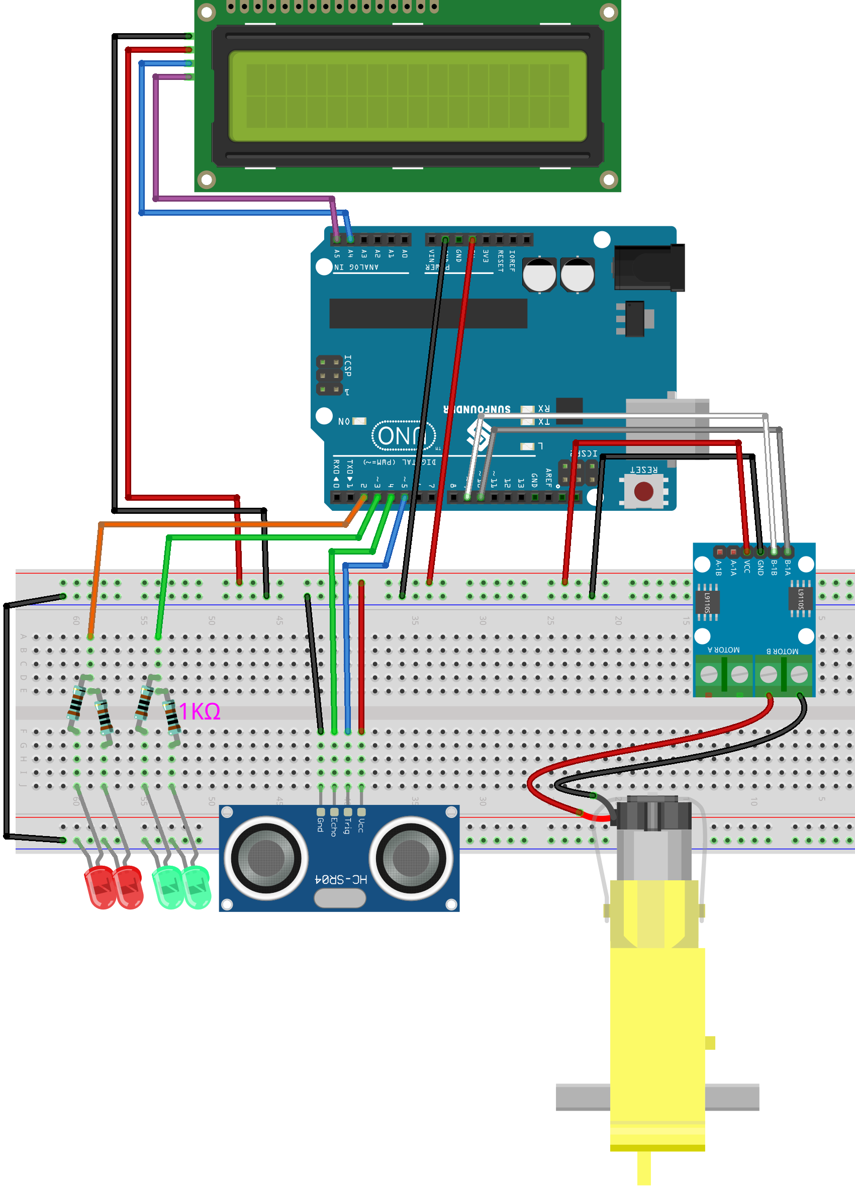
Common Connections:
Ultrasonic Sensor Module
Trig: Connect to 5 on the Arduino.
Echo: Connect to 4 on the Arduino.
GND: Connect to breadboard’s negative power bus.
VCC: Connect to breadboard’s red power bus.
TT Motor
Connect to MOTOR B on the L9110 Motor Driver Module.
L9110 Motor Driver Module
GND: Connect to breadboard’s negative power bus.
VCC: Connect to breadboard’s red power bus.
B-1B: Connect to 9 on the Arduino.
B-1A: Connect to 10 on the Arduino.
I2C LCD 1602
SDA: Connect to A4 on the Arduino.
SCL: Connect to A5 on the Arduino.
GND: Connect to breadboard’s negative power bus.
VCC: Connect to breadboard’s red power bus.
Writing the Code
Note
You can copy this code into Arduino IDE.
To install the library, use the Arduino Library Manager and search for LiquidCrystal I2C and install it.
Don’t forget to select the board(Arduino UNO R3) and the correct port before clicking the Upload button.
// Define pins for ultrasonic sensor, motor, and LEDs
const int echoPin = 5;
const int trigPin = 4;
const int motorB_1A = 9;
const int motorB_2A = 10;
const int redLED = 2;
const int greenLED = 3;

// Include the library code for LCD and I2C communication
#include <Wire.h>
#include <LiquidCrystal_I2C.h>

// Initialize the LCD on address 0x27 for a 16 characters and 2 line display
LiquidCrystal_I2C lcd(0x27, 16, 2);

int speed = 0; // Initialize speed at 0
unsigned long lastBlink = 0; // Last time the LED blinked
int ledState = LOW; // Current state of the red LED

void setup() {
  Serial.begin(9600); // Initialize serial communication at 9600 baud rate
  pinMode(echoPin, INPUT); // Set echo pin as input for receiving signals
  pinMode(trigPin, OUTPUT); // Set trig pin as output for sending signals
  pinMode(motorB_1A, OUTPUT); // Set motor control pin 1 as output
  pinMode(motorB_2A, OUTPUT); // Set motor control pin 2 as output
  pinMode(redLED, OUTPUT); // Set red LED pin as output
  pinMode(greenLED, OUTPUT); // Set green LED pin as output

  lcd.init();  // Initialize the LCD
  lcd.backlight();  // Turn on the backlight
}

void loop() {
  float distance = readSensorData(); // Get distance from ultrasonic sensor
  int intDistance = round(distance); // Round the distance to the nearest integer

  speed = intDistance < 6 ? 0 : (intDistance - 5) * 15;
  speed = min(speed, 255); // Ensure speed does not exceed 255

  controlMotor(speed); // Control motor speed based on updated speed

  unsigned long currentMillis = millis();

  // Control LED states based on distance
  if (intDistance < 5) {
    digitalWrite(redLED, HIGH); // Red LED stays on if distance is less than 5 cm
    digitalWrite(greenLED, LOW); // Green LED is off
  } else if (intDistance < 20) {
    // Blink red LED if distance is less than 20 cm
    if (currentMillis - lastBlink >= 250) { // Change the interval to control blink speed
      lastBlink = currentMillis;
      ledState = !ledState;
      digitalWrite(redLED, ledState);
    }
    digitalWrite(greenLED, LOW);
  } else {
    digitalWrite(redLED, LOW); // Turn off red LED if distance is 20 cm or more
    digitalWrite(greenLED, HIGH); // Green LED stays on if distance is more than 20 cm
  }

  // Update LCD display
  lcd.clear();
  lcd.setCursor(0, 0);
  lcd.print("Distance: ");
  lcd.print(intDistance);

  lcd.setCursor(0, 1);
  lcd.print("Speed: ");
  lcd.print(speed);

  delay(100); // Short delay to stabilize sensor readings
}

// Read and calculate distance from ultrasonic sensor
float readSensorData() {
  digitalWrite(trigPin, LOW); // Ensure a clean pulse
  delayMicroseconds(2);
  digitalWrite(trigPin, HIGH); // Send a high pulse for 10 microseconds
  delayMicroseconds(10);
  digitalWrite(trigPin, LOW); // End the pulse
  unsigned long duration = pulseIn(echoPin, HIGH); // Measure echo pulse width
  float distance = duration / 58.00; // Convert duration to distance in cm
  return distance;
}

// Adjust motor speed
void controlMotor(int speed) {
  analogWrite(motorB_1A, speed); // Set motor speed
  analogWrite(motorB_2A, 0); // Ensure motor runs in a single direction
}