Servo Control 2.0
Note
🌟 Welcome to the SunFounder Facebook Community! Whether you’re into Raspberry Pi, Arduino, or ESP32, you’ll find inspiration, help ideas here.
✅ Be the first to get free learning resources.
✅ Stay updated on new products & exclusive giveaways.
✅ Share your creations and get real feedback.
Kit purchase
Looking for parts? Check out our all-in-one kits below — packed with components, beginner-friendly guides, and tons of fun.

Name |
Includes Arduino board |
PURCHASE LINK |
|---|---|---|
Elite Explorer Kit |
Arduino Uno R4 WiFi |
|
Inventor Lab Kit |
Arduino Uno R3 |
Course Introduction
This Arduino project lets you control a servo motor with two buttons: the red button moves it toward 0° and the blue button toward 180°, with LEDs lighting up as feedback.
Note
If this is your first time working with an Arduino project, we recommend downloading and reviewing the basic materials first.
Required Components
In this project, we need the following components:
SN |
COMPONENT INTRODUCTION |
QUANTITY |
PURCHASE LINK |
|---|---|---|---|
1 |
Arduino UNO R4 WIFI |
1 |
|
2 |
USB Type-C cable |
1 |
|
3 |
Breadboard |
1 |
|
4 |
Wires |
Several |
|
5 |
Digital Servo Motor |
1 |
|
6 |
Button |
2 |
|
7 |
LED |
2 |
Wiring
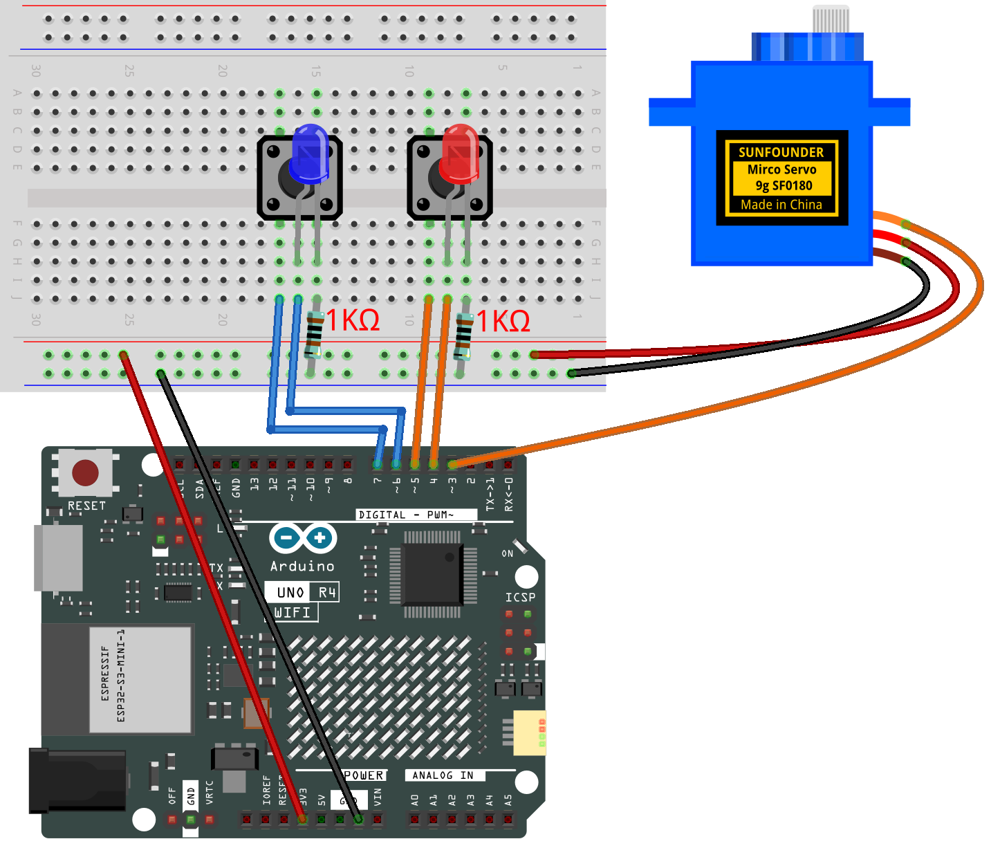
Common Connections:
Digital Servo Motor
Connect to breadboard’s positive power bus.
Connect to breadboard’s negative power bus.
Connect to 3 on the Arduino.
Button1
GND: Connect to a 1kΩ resistor, then to negative power bus on the breadboard
VCC: Connect to 7 on the Arduino.
Button2
GND: Connect to a 1kΩ resistor, then to negative power bus on the breadboard
VCC: Connect to 5 on the Arduino.
Blue LED
Connect the LED cathode to the to a 1kΩ resistor, then to negative power bus on the breadboard, anode to 6 on the Arduino.
Red LED
Connect the LED cathode to the to a 1kΩ resistor, then to negative power bus on the breadboard, anode to 4 on the Arduino.
Writing the Code
Note
You can copy this code into Arduino IDE.
Don’t forget to select the board(Arduino UNO R4 Minima/WIFI) and the correct port before clicking the Upload button.
#include <Servo.h>

// --- Pin definitions ---
const int servoPin = 3;   // Servo signal wire connected to pin 3
const int redLED   = 4;   // Red LED connected to pin 4 (with resistor)
const int redBtn   = 5;   // Red button connected to pin 5
const int blueLED  = 6;   // Blue LED connected to pin 6 (with resistor)
const int blueBtn  = 7;   // Blue button connected to pin 7

Servo myServo;             // Create a Servo object
int currentAngle = 90;     // Start servo at the middle position (90°)
const int stepSize = 5;    // Servo moves 3° for each button press

// Variables to remember the last button states
bool lastRedState  = HIGH; // HIGH means not pressed (because of INPUT_PULLUP)
bool lastBlueState = HIGH;

void setup() {
  myServo.attach(servoPin);       // Attach the servo to pin 3
  myServo.write(currentAngle);    // Move servo to initial position

  pinMode(redLED, OUTPUT);        // Set LED pins as outputs
  pinMode(blueLED, OUTPUT);

  pinMode(redBtn, INPUT_PULLUP);  // Use internal pull-up resistor
  pinMode(blueBtn, INPUT_PULLUP); // Button is active LOW
}

void loop() {
  // Read current button states
  bool redPressed  = (digitalRead(redBtn)  == LOW); // LOW means pressed
  bool bluePressed = (digitalRead(blueBtn) == LOW);

  // --- Red button logic ---
  if (redPressed && lastRedState == HIGH) { // Detect new press (not held down)
    delay(50);                              // Small delay to debounce
    if (digitalRead(redBtn) == LOW) {       // Check again to confirm press
      digitalWrite(redLED, HIGH);           // Turn on red LED
      currentAngle = max(0, currentAngle - stepSize); // Move 3° toward 0°
      myServo.write(currentAngle);          // Update servo position
    }
  } else {
    digitalWrite(redLED, LOW);              // Turn off LED when not pressed
  }

  // --- Blue button logic ---
  if (bluePressed && lastBlueState == HIGH) { // Detect new press
    delay(50);                                // Debounce
    if (digitalRead(blueBtn) == LOW) {        // Confirm press
      digitalWrite(blueLED, HIGH);            // Turn on blue LED
      currentAngle = min(180, currentAngle + stepSize); // Move 3° toward 180°
      myServo.write(currentAngle);            // Update servo position
    }
  } else {
    digitalWrite(blueLED, LOW);               // Turn off LED when not pressed
  }

  // Remember button states for next loop
  lastRedState  = redPressed;
  lastBlueState = bluePressed;
}