Speed Detection 3.0
Note
🌟 Welcome to the SunFounder Facebook Community! Whether you’re into Raspberry Pi, Arduino, or ESP32, you’ll find inspiration, help ideas here.
✅ Be the first to get free learning resources.
✅ Stay updated on new products & exclusive giveaways.
✅ Share your creations and get real feedback.
Kit purchase
Looking for parts? Check out our all-in-one kits below — packed with components, beginner-friendly guides, and tons of fun.

Name |
Includes Arduino board |
PURCHASE LINK |
|---|---|---|
Elite Explorer Kit |
Arduino Uno R4 WiFi |
|
3 in 1 Ultimate Starter Kit |
Arduino Uno R4 Minima |
Course Introduction
This Arduino project functions as a basic speed detection system using two Ultrasonic Sensor Modules and an LCD display and buzzer moudle. When an object passes the first sensor, a timer starts; it stops at the second sensor.
Note
If this is your first time working with an Arduino project, we recommend downloading and reviewing the basic materials first.
Required Components
In this project, we need the following components:
SN |
COMPONENT INTRODUCTION |
QUANTITY |
PURCHASE LINK |
|---|---|---|---|
1 |
Arduino UNO R4 Minima |
1 |
|
2 |
USB Type-C cable |
1 |
|
3 |
Breadboard |
1 |
|
4 |
Wires |
Several |
|
5 |
I2C LCD 1602 |
1 |
|
6 |
Ultrasonic Sensor Module |
2 |
|
7 |
Buzzer Modudle |
1 |
Wiring
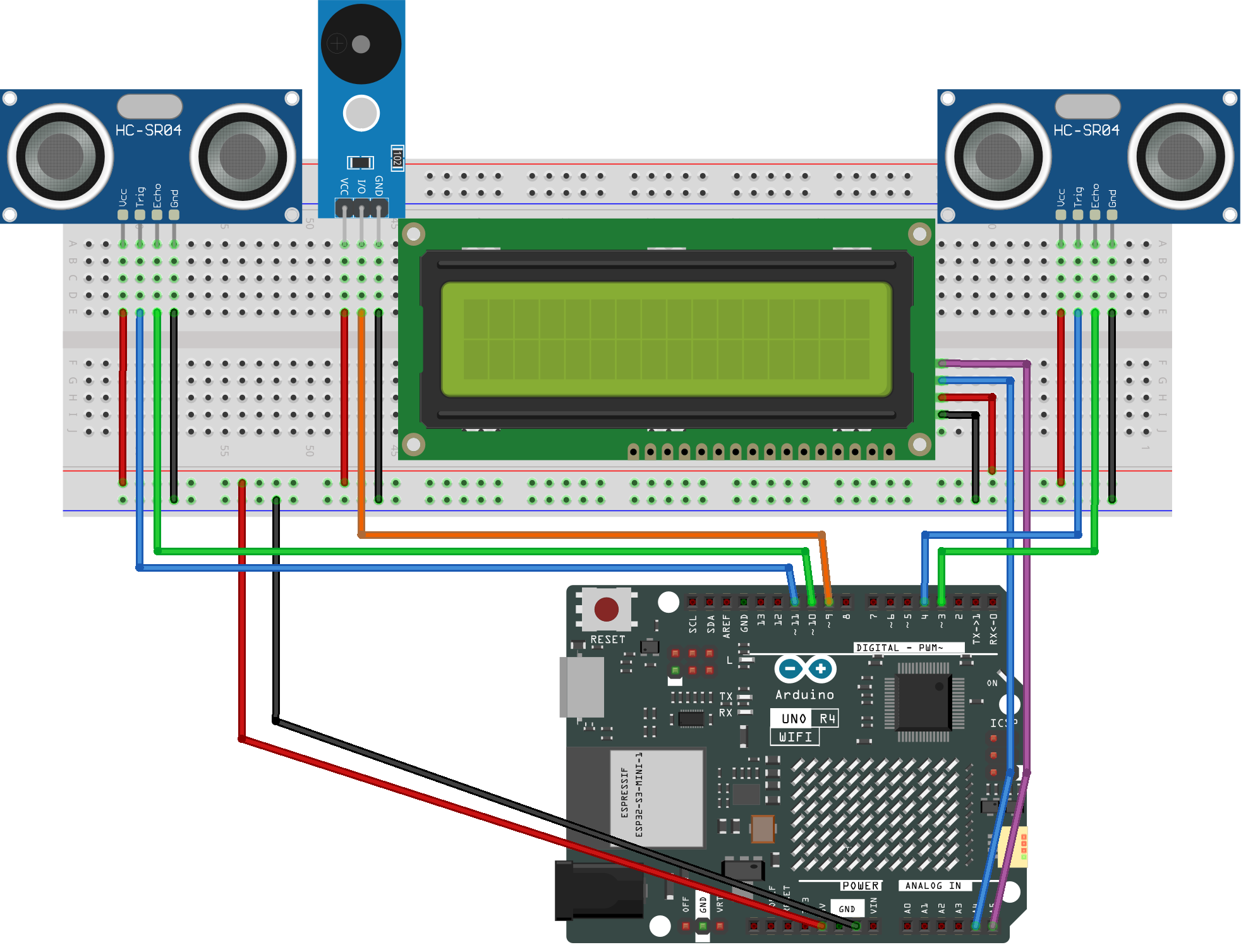
Common Connections:
I2C LCD 1602
SDA: Connect to A4 on the Arduino.
SCL: Connect to A5 on the Arduino.
GND: Connect to breadboard’s negative power bus.
VCC: Connect to breadboard’s red power bus.
Ultrasonic Sensor Module Front
Trig: Connect to 4 on the Arduino.
Echo: Connect to 3 on the Arduino.
GND: Connect to breadboard’s negative power bus.
VCC: Connect to breadboard’s red power bus.
Ultrasonic Sensor Module Back
Trig: Connect to 11 on the Arduino.
Echo: Connect to 10 on the Arduino.
GND: Connect to breadboard’s negative power bus.
VCC: Connect to breadboard’s red power bus.
Buzzer Module
I/0: Connect to 9 on the Arduino.
+: Connect to breadboard’s red power bus.
-: Connect to breadboard’s negative power bus.
Writing the Code
Note
You can copy this code into Arduino IDE.
To install the library, use the Arduino Library Manager and search for LiquidCrystal I2C and install it.
Don’t forget to select the board(Arduino UNO R4 Minima/WIFI) and the correct port before clicking the Upload button.
#include <Wire.h>
#include <LiquidCrystal_I2C.h>

// ---------------- LCD ----------------
// I2C LCD (address: 0x27, 16x2)
LiquidCrystal_I2C lcd(0x27, 16, 2);

// ---------------- Ultrasonic Sensor Pins ----------------
// Front ultrasonic sensor
#define TRIG1 4
#define ECHO1 3

// Back ultrasonic sensor
#define TRIG2 11
#define ECHO2 10

// ---------------- Passive Buzzer ----------------
#define BUZZER_PIN 9

// ---------------- Parameters ----------------
float gateDistance = 1.30;   // Distance between two sensors (meters)
float speedLimit   = 40.0;   // Speed limit (km/h)
float triggerDist  = 15.0;   // Detection distance (cm)

// ---------------- State Variables ----------------
bool firstGateTriggered = false;
bool speedCalculated    = false;

unsigned long t1 = 0;
unsigned long t2 = 0;

// ---------------- Ultrasonic Distance Function ----------------
// Measure distance using ultrasonic sensor (return: cm)
float getDistanceCM(int trigPin, int echoPin) {
  digitalWrite(trigPin, LOW);
  delayMicroseconds(2);
  digitalWrite(trigPin, HIGH);
  delayMicroseconds(10);
  digitalWrite(trigPin, LOW);

  long duration = pulseIn(echoPin, HIGH, 30000);
  if (duration == 0) return -1;

  return duration * 0.034 / 2;
}

void setup() {
  // Set pin modes for ultrasonic sensors
  pinMode(TRIG1, OUTPUT);
  pinMode(ECHO1, INPUT);
  pinMode(TRIG2, OUTPUT);
  pinMode(ECHO2, INPUT);

  // Set buzzer pin as output
  pinMode(BUZZER_PIN, OUTPUT);

  // Initialize LCD
  lcd.init();
  lcd.backlight();

  // Show startup message
  lcd.setCursor(0, 0);
  lcd.print("Speed Detector");
  lcd.setCursor(0, 1);
  lcd.print("Waiting...");
}

void loop() {
  // Read distances from both ultrasonic sensors
  float d1 = getDistanceCM(TRIG1, ECHO1);
  delay(40);  // Prevent ultrasonic interference
  float d2 = getDistanceCM(TRIG2, ECHO2);

  // First sensor detects object
  if (!firstGateTriggered && d1 > 0 && d1 < triggerDist) {
    firstGateTriggered = true;
    t1 = millis();

    lcd.clear();
    lcd.setCursor(0, 0);
    lcd.print("Vehicle detected");
    lcd.setCursor(0, 1);
    lcd.print("Measuring...");
  }

  // Second sensor detects object
  if (firstGateTriggered && !speedCalculated && d2 > 0 && d2 < triggerDist) {
    t2 = millis();
    speedCalculated = true;

    float deltaT = (t2 - t1) / 1000.0;

    lcd.clear();

    if (deltaT > 0.05) {  // Ignore false trigger
      float speed = (gateDistance / deltaT) * 3.6;

      lcd.setCursor(0, 0);
      lcd.print("Speed:");
      lcd.print(speed, 1);
      lcd.print("km/h");

      lcd.setCursor(0, 1);
      if (speed > speedLimit) {
        lcd.print("Over Speed!");

        // Beep 3 times
        for (int i = 0; i < 3; i++) {
          tone(BUZZER_PIN, 2000);
          delay(200);
          noTone(BUZZER_PIN);
          delay(200);
        }
      } else {
        lcd.print("Normal");
      }
    } else {
      lcd.print("Invalid data");
    }

    delay(3000);

    // Reset system
    firstGateTriggered = false;
    speedCalculated = false;

    lcd.clear();
    lcd.setCursor(0, 0);
    lcd.print("Speed Detector");
    lcd.setCursor(0, 1);
    lcd.print("Waiting...");
  }
}