LED control 2.0
Note
🌟 Welcome to the SunFounder Facebook Community! Whether you’re into Raspberry Pi, Arduino, or ESP32, you’ll find inspiration, help ideas here.
✅ Be the first to get free learning resources.
✅ Stay updated on new products & exclusive giveaways.
✅ Share your creations and get real feedback.
Kit purchase
Looking for parts? Check out our all-in-one kits below — packed with components, beginner-friendly guides, and tons of fun.

Name |
Includes Arduino board |
PURCHASE LINK |
|---|---|---|
Ultimate Sensor Kit |
Arduino Uno R4 Minima |
|
Elite Explorer Kit |
Arduino Uno R4 WiFi |
|
3 in 1 Ultimate Starter Kit |
Arduino Uno R4 Minima |
|
Universal Maker Sensor Kit |
× |
Course Introduction
In this lesson, you will use Arduino together with two IR obstacle sensors and a row of LEDs to create an automatic directional light-flow effect.
When the left sensor detects an object, the LEDs light up in a forward flowing pattern. When the right sensor is triggered, the LEDs flow in the opposite direction.
Each sensor controls one direction of the animation, allowing the LEDs to respond dynamically based on which side an obstacle is detected.
Note
If this is your first time working with an Arduino project, we recommend downloading and reviewing the basic materials first.
Required Components
In this project, we need the following components:
SN |
COMPONENT INTRODUCTION |
QUANTITY |
PURCHASE LINK |
|---|---|---|---|
1 |
Arduino UNO R4 Minima |
1 |
|
2 |
USB Type-C cable |
1 |
|
3 |
Breadboard |
1 |
|
4 |
Wires |
Several |
|
5 |
1kΩ resistor |
Several |
|
6 |
IR Obstacle Avoidance Sensor Module |
2 |
|
7 |
LED |
Several |
Wiring
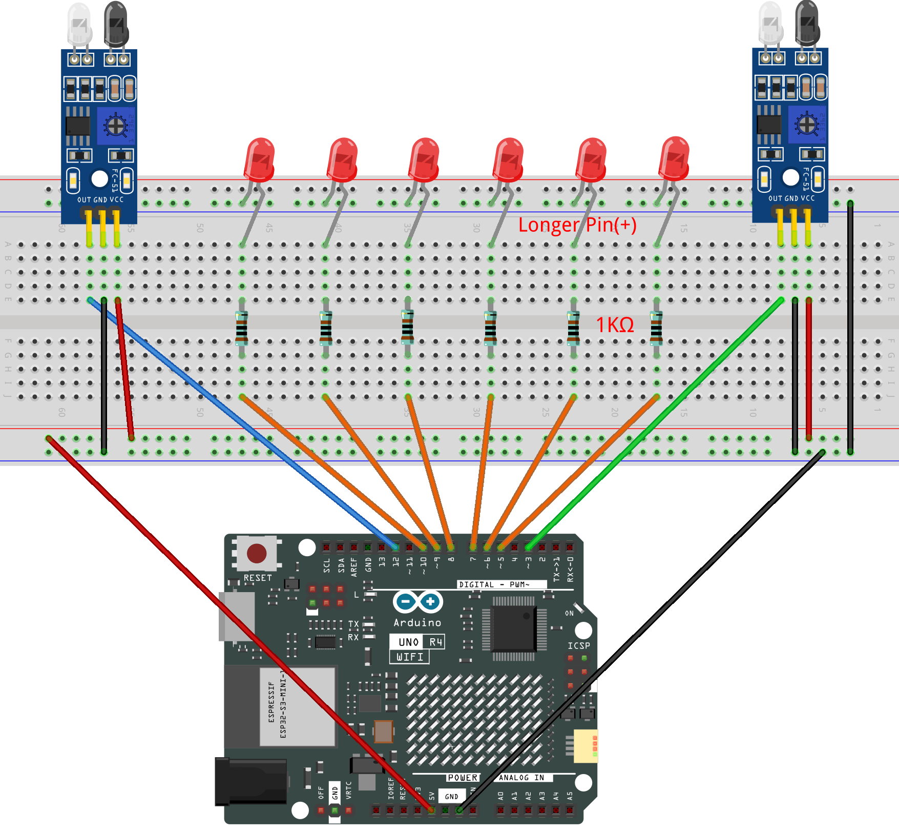
Common Connections:
LED
Connect the LEDs cathode to the negative power bus on the breadboard, and the LEDs anode to 1kΩ resistor then to 5 to 10 on the Arduino.
IR Obstacle Avoidance Sensor Module 1
OUT: Connect to 3 on the Arduino.
GND: Connect to breadboard’s negative power bus.
VCC: Connect to breadboard’s red power bus.
IR Obstacle Avoidance Sensor Module 2
OUT: Connect to 12 on the Arduino.
GND: Connect to breadboard’s negative power bus.
VCC: Connect to breadboard’s red power bus.
Writing the Code
Note
You can copy this code into Arduino IDE.
Don’t forget to select the board(Arduino UNO R4 Minima) and the correct port before clicking the Upload button.
// Obstacle sensors
// These sensors output LOW when an object is detected
const int sensorLeft  = 3;     // Triggers forward flow
const int sensorRight = 12;    // Triggers backward flow

// LED pins in order from left to right
const int ledPins[] = {5, 6, 7, 8, 9, 10};
const int ledCount = 6;

// Time between LED steps
int delayTime = 80;

void setup() {

  // Set all LEDs as outputs
  for (int i = 0; i < ledCount; i++) {
    pinMode(ledPins[i], OUTPUT);
  }

  // Sensors are digital inputs
  pinMode(sensorLeft, INPUT);
  pinMode(sensorRight, INPUT);
}

void loop() {

  // Read sensors (LOW means obstacle found)
  bool leftDetected  = (digitalRead(sensorLeft) == LOW);
  bool rightDetected = (digitalRead(sensorRight) == LOW);

  // Forward flow: LEDs move from pin 5 → 10
  if (leftDetected) {
    for (int i = 0; i < ledCount; i++) {
      digitalWrite(ledPins[i], HIGH);   // Light current LED
      delay(delayTime);

      if (i > 0) {
        digitalWrite(ledPins[i - 1], LOW); // Turn off previous LED
      }
    }
    digitalWrite(ledPins[ledCount - 1], LOW); // Clear last LED
  }

  // Backward flow: LEDs move from pin 10 → 5
  if (rightDetected) {
    for (int i = ledCount - 1; i >= 0; i--) {
      digitalWrite(ledPins[i], HIGH);   // Light current LED
      delay(delayTime);

      if (i < ledCount - 1) {
        digitalWrite(ledPins[i + 1], LOW); // Turn off previous LED
      }
    }
    digitalWrite(ledPins[0], LOW); // Clear last LED
  }
}