Running Light 1.0
Note
🌟 Welcome to the SunFounder Facebook Community! Whether you’re into Raspberry Pi, Arduino, or ESP32, you’ll find inspiration, help ideas here.
✅ Be the first to get free learning resources.
✅ Stay updated on new products & exclusive giveaways.
✅ Share your creations and get real feedback.
Kit purchase
Looking for parts? Check out our all-in-one kits below — packed with components, beginner-friendly guides, and tons of fun.

Name |
Includes Arduino board |
PURCHASE LINK |
|---|---|---|
Ultimate Sensor Kit |
Arduino Uno R4 Minima |
|
Elite Explorer Kit |
Arduino Uno R4 WiFi |
|
3 in 1 Ultimate Starter Kit |
Arduino Uno R4 Minima |
|
Universal Maker Sensor Kit |
× |
Course Introduction
In this lesson, you will learn how to use Arduino with LEDs, a potentiometer, a button, and an active buzzer to create a running light effect.
Rotate the potentiometer to adjust the speed of the flowing LEDs. Press the button to pause the light at its current position or resume the animation, while the buzzer beeps in sync with the movement.
Note
If this is your first time working with an Arduino project, we recommend downloading and reviewing the basic materials first.
Required Components
In this project, we need the following components:
SN |
COMPONENT INTRODUCTION |
QUANTITY |
PURCHASE LINK |
|---|---|---|---|
1 |
Arduino UNO R4 Minima |
1 |
|
2 |
USB Type-C cable |
1 |
|
3 |
Breadboard |
1 |
|
4 |
Wires |
Several |
|
5 |
220 resistor |
Several |
|
6 |
Button |
1 |
|
7 |
LED |
Several |
|
8 |
Active Buzzer |
1 |
|
9 |
Potentiometer Sensor Module |
1 |
Wiring
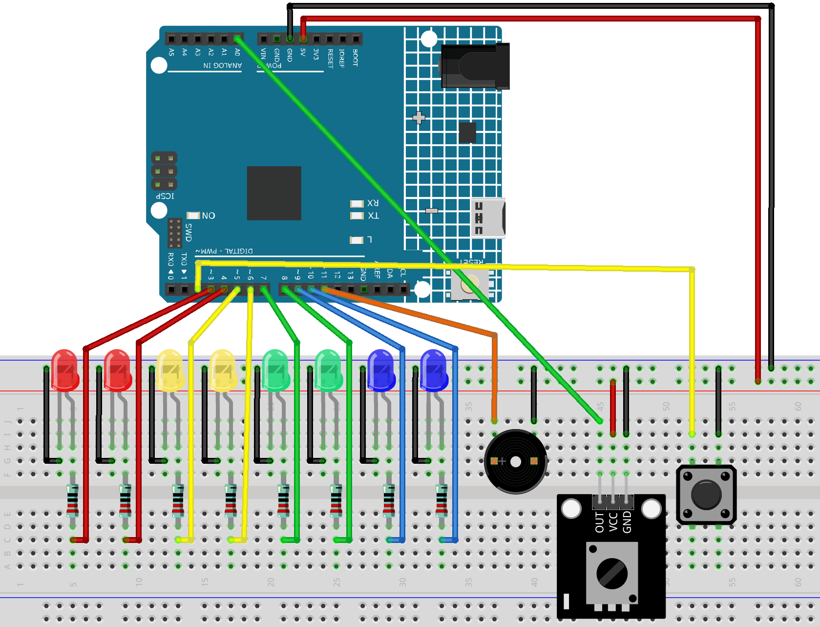
Common Connections:
LED
Connect the LEDs cathode to the negative power bus on the breadboard, and the LEDs anode to a 220Ω resistor then to 3 to 10 on the Arduino.
Button
Connect to breadboard’s negative power bus.
Connect to 2 on the Arduino.
Active Buzzer
+: Connect to 11 on the Arduino.
-: Connect to breadboard’s negative power bus.
Potentiometer Sensor Module
OUT: Connect to A0 on the Arduino.
GND: Connect to breadboard’s negative power bus.
VCC: Connect to breadboard’s red power bus.
Writing the Code
Note
You can copy this code into Arduino IDE.
Don’t forget to select the board(Arduino UNO R4 Minima) and the correct port before clicking the Upload button.
// LED pins
const int ledPins[] = {3, 4, 5, 6, 7, 8, 9, 10};
const int ledCount = 8;

// Potentiometer pin
const int POT_PIN = A0;

// Button pin
const int BUTTON_PIN = 2;

// Active buzzer pin
const int BUZZER_PIN = 11;

int currentLed = 0;
bool isRunning = true;

unsigned long lastLedTime = 0;
unsigned long lastButtonTime = 0;
unsigned long buzzerStartTime = 0;

const unsigned long debounceDelay = 200;
const unsigned long buzzerBeepTime = 40;

bool lastButtonState = HIGH;
bool buzzerActive = false;

void setup() {
  for (int i = 0; i < ledCount; i++) {
    pinMode(ledPins[i], OUTPUT);
    digitalWrite(ledPins[i], LOW);
  }

  pinMode(BUTTON_PIN, INPUT_PULLUP);
  pinMode(BUZZER_PIN, OUTPUT);

  digitalWrite(BUZZER_PIN, LOW);
  digitalWrite(ledPins[currentLed], HIGH);
}

void loop() {
  handleButton();
  handleBuzzer();

  if (isRunning) {
    int potValue = analogRead(POT_PIN);

    // Adjust flowing speed with the potentiometer
    int flowDelay = map(potValue, 0, 1023, 80, 800);

    if (millis() - lastLedTime >= flowDelay) {
      lastLedTime = millis();

      digitalWrite(ledPins[currentLed], LOW);

      currentLed++;
      if (currentLed >= ledCount) {
        currentLed = 0;
      }

      digitalWrite(ledPins[currentLed], HIGH);

      beepOnce();
    }
  }
}

void handleButton() {
  bool currentButtonState = digitalRead(BUTTON_PIN);

  if (lastButtonState == HIGH && currentButtonState == LOW) {
    if (millis() - lastButtonTime > debounceDelay) {
      isRunning = !isRunning;
      lastButtonTime = millis();

      beepOnce();

      if (!isRunning) {
        delay(60);
        digitalWrite(BUZZER_PIN, LOW);
        buzzerActive = false;
      }
    }
  }

  lastButtonState = currentButtonState;
}

void beepOnce() {
  digitalWrite(BUZZER_PIN, HIGH);
  buzzerStartTime = millis();
  buzzerActive = true;
}

void handleBuzzer() {
  if (buzzerActive && millis() - buzzerStartTime >= buzzerBeepTime) {
    digitalWrite(BUZZER_PIN, LOW);
    buzzerActive = false;
  }
}