Finger Count 3.0
Note
🌟 Welcome to the SunFounder Facebook Community! Whether you’re into Raspberry Pi, Arduino, or ESP32, you’ll find inspiration, help ideas here.
✅ Be the first to get free learning resources.
✅ Stay updated on new products & exclusive giveaways.
✅ Share your creations and get real feedback.
Kit purchase
Looking for parts? Check out our all-in-one kits below — packed with components, beginner-friendly guides, and tons of fun.

Name |
Includes Arduino board |
PURCHASE LINK |
|---|---|---|
Ultimate Sensor Kit |
Arduino Uno R4 Minima |
|
Elite Explorer Kit |
Arduino Uno R4 WiFi |
|
3 in 1 Ultimate Starter Kit |
Arduino Uno R4 Minima |
|
Universal Maker Sensor Kit |
× |
Course Introduction
In this lesson, we control a servo to open the gate using the gesture password 5-1-5, and close it with the gesture 4, based on data received via serial communication.
Red and green LEDs indicate the gate status: by default, the gate is closed with the red LED on; when the correct password is entered, the gate opens and the green LED lights up.
This code controls the servo and LEDs on an Arduino Uno by receiving finger count data from a Python script, which detects the number of fingers shown to a camera and sends the data to the Arduino via serial communication.
Note
If this is your first time working with an Arduino project, we recommend downloading and reviewing the basic materials first.
Required Components
In this project, we need the following components:
SN |
COMPONENT INTRODUCTION |
QUANTITY |
PURCHASE LINK |
|---|---|---|---|
1 |
Arduino UNO R4 WIFI |
1 |
|
2 |
USB Type-C cable |
1 |
|
3 |
Breadboard |
1 |
|
4 |
Wires |
Several |
|
5 |
1kΩ resistor |
Several |
|
6 |
LED |
Several |
|
7 |
Digital Servo Motor |
1 |
Wiring
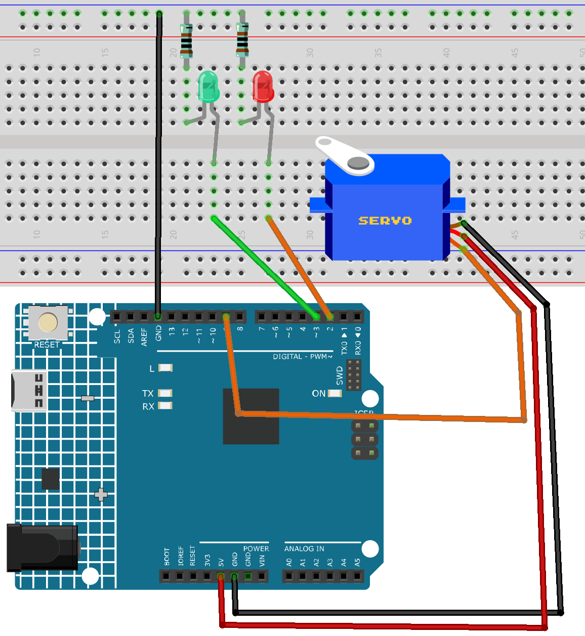
Common Connections:
LED
Connect the LEDs cathode to a 1kΩ resistor then to the negative power bus on the breadboard, and the LEDs anode to the 2 to 3 on the Arduino.
Digital Servo Motor
Connect to breadboard’s positive power bus.
Connect to breadboard’s negative power bus.
Connect to 9 on the Arduino.
Operating Steps
Note
Copy the following code into Arduino IDE.
Use the Arduino Library Manager and search for Servo.h install library.
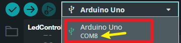
Select the board(Arduino UNO R4 WIFI) and the correct port before clicking the Upload button.
Then use the Python code
FingerCountSender(2). You can click hereFingerCountSender(2).zipto download it.- Update the Python script to use the correct serial port(COMx), ensuring it matches the one identified during Arduino setup(COMx).
Then run the python code to open the camera window.
#include <Servo.h>

// LED pins
const int redLedPin = 2;
const int greenLedPin = 3;

// Servo object and pin
Servo gateServo;
const int servoPin = 9;

// Servo angle definitions
const int GATE_CLOSED = 90;
const int GATE_OPEN = 0;

// Array to store gesture input sequence
int gestureSequence[3] = {-1, -1, -1}; // Initially empty
const int expectedSequence[3] = {5, 1, 5}; // Password sequence

bool gateOpen = false;

void setup() {
  pinMode(redLedPin, OUTPUT);
  pinMode(greenLedPin, OUTPUT);
  digitalWrite(redLedPin, HIGH);   // Default: red LED on
  digitalWrite(greenLedPin, LOW);

  gateServo.attach(servoPin);
  gateServo.write(GATE_CLOSED); // Default: gate closed

  Serial.begin(115200);
  Serial.setTimeout(1);
}

void loop() {
  // Listen for serial data
  if (Serial.available() > 0) {
    int value = Serial.readString().toInt();

    // Only accept values from 0 to 5 (finger count)
    if (value >= 0 && value <= 5) {
      updateGestureSequence(value);

      // Check if gesture matches 5-1-5
      if (isCorrectSequence()) {
        openGate();
      }
    }
  }
}

// Update gesture input sequence array
void updateGestureSequence(int newValue) {
  gestureSequence[0] = gestureSequence[1];
  gestureSequence[1] = gestureSequence[2];
  gestureSequence[2] = newValue;
}

// Check if the input sequence matches the expected password
bool isCorrectSequence() {
  for (int i = 0; i < 3; i++) {
    if (gestureSequence[i] != expectedSequence[i]) {
      return false;
    }
  }
  return true;
}

void openGate() {
  if (!gateOpen) {
    Serial.println("✅ Correct gesture password. Gate opening.");
    gateServo.write(GATE_OPEN);
    digitalWrite(greenLedPin, HIGH);
    digitalWrite(redLedPin, LOW);
    gateOpen = true;
  }
}