Gas Leak Monitor
Note
🌟 Welcome to the SunFounder Facebook Community! Whether you’re into Raspberry Pi, Arduino, or ESP32, you’ll find inspiration, help ideas here.
✅ Be the first to get free learning resources.
✅ Stay updated on new products & exclusive giveaways.
✅ Share your creations and get real feedback.
Kit purchase
Looking for parts? Check out our all-in-one kits below — packed with components, beginner-friendly guides, and tons of fun.

Name |
Includes Arduino board |
PURCHASE LINK |
|---|---|---|
Ultimate Sensor Kit |
Arduino Uno R4 Minima |
|
Universal Maker Sensor Kit |
× |
Course Introduction
This Arduino project simulates a basic gas leak detection system using an MQ-2 gas sensor, a red LED, and a buzzer.
The sensor continuously monitors gas concentration. If the reading exceeds a set threshold, the buzzer sounds and the LED blinks to indicate danger.
Otherwise, the system remains silent and the LED stays off.
Note
If this is your first time working with an Arduino project, we recommend downloading and reviewing the basic materials first.
Required Components
In this project, we need the following components:
SN |
COMPONENT INTRODUCTION |
QUANTITY |
PURCHASE LINK |
|---|---|---|---|
1 |
Arduino UNO R4 WIFI |
1 |
|
2 |
USB Type-C cable |
1 |
|
3 |
Breadboard |
1 |
|
4 |
Wires |
Several |
|
5 |
Buzzer Modudle |
1 |
|
6 |
LED |
1 |
|
7 |
MQ-2 Gas Sensor Module |
1 |
|
8 |
220Ω resistor |
1 |
Wiring
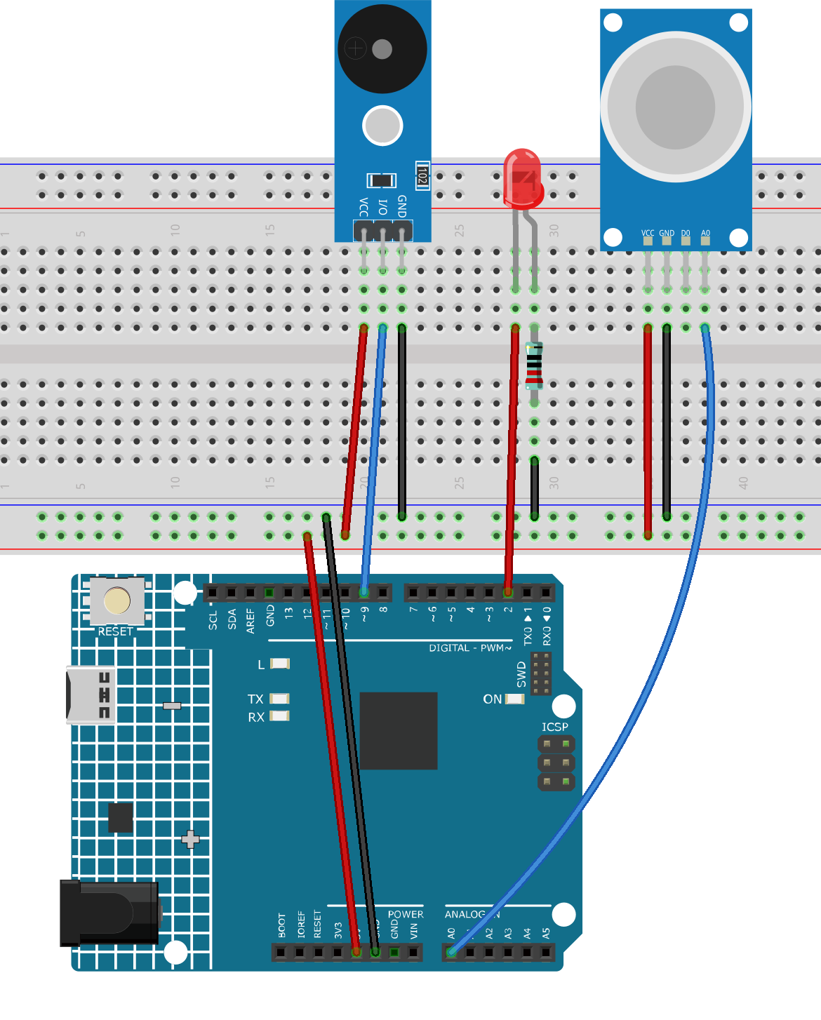
Common Connections:
MQ-2 Gas Sensor Module
A0: Connect to A0 on the Arduino.
GND: Connect to breadboard’s negative power bus.
VCC: Connect to breadboard’s red power bus.
Buzzer Modudle
I/O: Connect to 9 on the Arduino.
GND: Connect to breadboard’s negative power bus.
VCC: Connect to breadboard’s red power bus.
LED
Connect the LED anode to 2 on the Arduino, and the cathode to a 220Ω resistor, then to the negative power bus on the breadboard.
Writing the Code
Note
You can copy this code into Arduino IDE.
Don’t forget to select the board(Arduino UNO R4 WIFI) and the correct port before clicking the Upload button.
/*
  Demo program: Arduino Uno + MQ-2 gas sensor + red LED + buzzer.
  Purpose: Simulate gas leak detection.
  - If gas concentration > threshold (300): buzzer sounds, red LED blinks.
  - Otherwise: buzzer is silent, red LED is off.

  Hardware:
  - MQ-2 gas sensor connected to A0
  - Buzzer connected to D9
  - Red LED connected to D2 (via resistor)
*/

const int sensorPin = A0;       // MQ-2 sensor analog pin
const int buzzerPin = 9;        // Buzzer pin
const int redLEDPin = 2;        // Red LED pin

int sensorValue = 0;            // Variable to store sensor value
const int threshold = 90;      // Gas detection threshold

void setup() {
  Serial.begin(9600);           // Initialize serial monitor
  pinMode(buzzerPin, OUTPUT);   // Set buzzer pin as output
  pinMode(redLEDPin, OUTPUT);   // Set red LED pin as output
}

void loop() {o
  sensorValue = analogRead(sensorPin);  // Read sensor value
  Serial.print("Analog output: ");
  Serial.println(sensorValue);

  if (sensorValue > threshold) {
    tone(buzzerPin, 500);              // Turn on buzzer
    digitalWrite(redLEDPin, HIGH);     // LED ON
    delay(250);                        // Wait 250 ms
    digitalWrite(redLEDPin, LOW);      // LED OFF
    delay(250);                        // Wait 250 ms (total blink cycle = 500 ms)
  } else {
    noTone(buzzerPin);                 // Turn off buzzer
    digitalWrite(redLEDPin, LOW);      // LED OFF
    delay(50);                         // Short delay
  }
}