6.5 Color Gradient
Are you ready to experience a world of color? This project will take you on a magical journey where you can control an RGB LED and achieve smooth color transitions. Whether you’re looking to add some color to your home decor or seeking a fun programming project, this project has got you covered. Let’s dive into this colorful world together!
Required Components
In this project, we need the following components.
It’s definitely convenient to buy a whole kit, here’s the link:
Name |
ITEMS IN THIS KIT |
LINK |
|---|---|---|
ESP32 Starter Kit |
320+ |
You can also buy them separately from the links below.
COMPONENT INTRODUCTION |
PURCHASE LINK |
|---|---|
- |
|
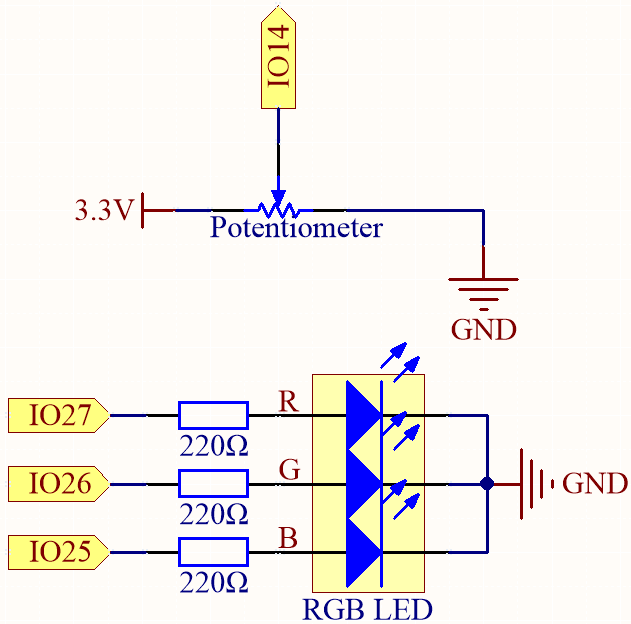
Schematic
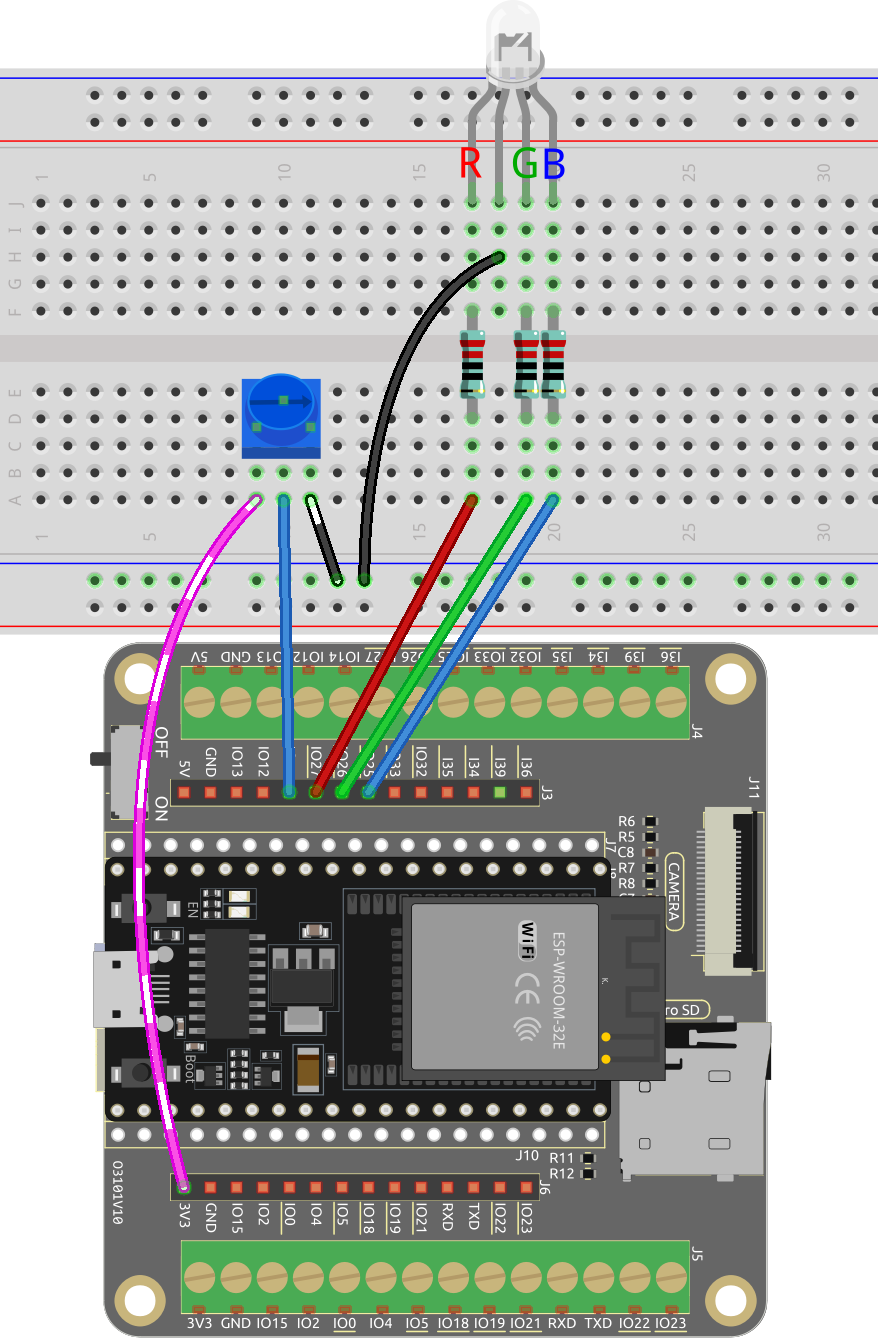
Wiring
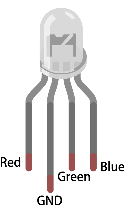
The RGB LED has 4 pins: the long pin is the common cathode pin, which is usually connected to GND; the left pin next to the longest pin is Red; and the two pins on the right are Green and Blue.
Code
Note
You can open the file
6.5_color_gradient.inounder the path ofesp32-starter-kit-main\c\codes\6.5_color_gradient.After selecting the board (ESP32 Dev Module) and the appropriate port, click the Upload button.
This project uses an RGB LED and a potentiometer to create a color mixing effect. The potentiometer is used to adjust the hue value of the LED, which is then converted into RGB values using a color conversion function. The RGB values are then used to update the color of the LED.
How it works?
This project builds upon the 2.3 Colorful Light project by adding a potentiometer to adjust the hue value of the LED. The hue value is then converted to RGB values using a color conversion function.
In the loop function, read the value of the potentiometer and convert it to a hue value (0-360).
int knobValue = analogRead(KNOB_PIN);
float hueValue = (float) knobValue / 4095.0;
int hue = (int) (hueValue * 360);
Convert the hue value to RGB values using the
HUEtoRGB()function, and update the LED with the new color values.int red, green, blue; HUEtoRGB(hue, &red, &green, &blue); setColor(red, green, blue);
The
setColor()function sets the value of the red, green, and blue channels using theLEDClibrary.void setColor(int red, int green, int blue) { ledcWrite(redChannel, red); ledcWrite(greenChannel, green); ledcWrite(blueChannel, blue); }
The
HUEtoRGBfunction converts a hue value to RGB values using the HSL color model.void HUEtoRGB(int hue, int* red, int* green, int* blue) { float h = (float) hue / 60.0; float c = 1.0; float x = c * (1.0 - fabs(fmod(h, 2.0) - 1.0)); float r, g, b; if (h < 1.0) { r = c; g = x; b = 0; ...