Note
Hello, welcome to the SunFounder Raspberry Pi & Arduino & ESP32 Enthusiasts Community on Facebook! Dive deeper into Raspberry Pi, Arduino, and ESP32 with fellow enthusiasts.
Why Join?
Expert Support: Solve post-sale issues and technical challenges with help from our community and team.
Learn & Share: Exchange tips and tutorials to enhance your skills.
Exclusive Previews: Get early access to new product announcements and sneak peeks.
Special Discounts: Enjoy exclusive discounts on our newest products.
Festive Promotions and Giveaways: Take part in giveaways and holiday promotions.
👉 Ready to explore and create with us? Click [here] and join today!
5.2 Tilt It!
The tilt switch is a simple yet effective 2-pin device that contains a metal ball in its center. When the switch is in an upright position, the two pins are electrically connected, allowing current to flow through. However, when the switch is tilted or tilted at a certain angle, the metal ball moves and breaks the electrical connection between the pins.
In this project, we will utilize the tilt switch to control the illumination of an LED. By positioning the switch in a way that triggers the tilt action, we can toggle the LED on and off based on the switch’s orientation.
Required Components
In this project, we need the following components.
It’s definitely convenient to buy a whole kit, here’s the link:
Name |
ITEMS IN THIS KIT |
LINK |
|---|---|---|
ESP32 Starter Kit |
320+ |
You can also buy them separately from the links below.
COMPONENT INTRODUCTION |
PURCHASE LINK |
|---|---|
- |
Available Pins
Available Pins
Here is a list of available pins on the ESP32 board for this project.
For Input
IO14, IO25, I35, I34, I39, I36, IO18, IO19, IO21, IO22, IO23
For Output
IO13, IO12, IO14, IO27, IO26, IO25, IO33, IO32, IO15, IO2, IO0, IO4, IO5, IO18, IO19, IO21, IO22, IO23
Conditional Usage Pins (Input)
The following pins have built-in pull-up or pull-down resistors, so external resistors are not required when using them as input pins:
Conditional Usage Pins
Description
IO13, IO15, IO2, IO4
Pulling up with a 47K resistor defaults the value to high.
IO27, IO26, IO33
Pulling up with a 4.7K resistor defaults the value to high.
IO32
Pulling down with a 1K resistor defaults the value to low.
Strapping Pins (Input)
Strapping pins are a special set of pins that are used to determine specific boot modes during device startup (i.e., power-on reset).
Strapping Pins
IO5, IO0, IO2, IO12, IO15
Generally, it is not recommended to use them as input pins. If you wish to use these pins, consider the potential impact on the booting process. For more details, please refer to the Strapping Pins section.
Schematic
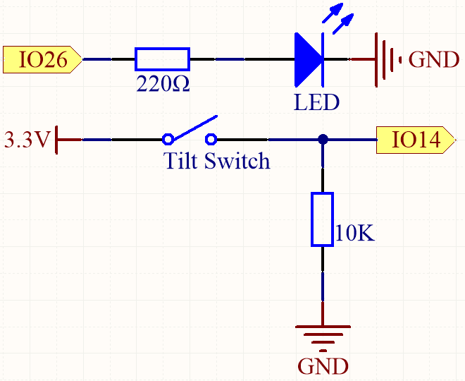
When the tilt switch is in an upright position, IO14 will be set to high, resulting in the LED being lit. Conversely, when the tilt switch is tilted, IO14 will be set to low, causing the LED to turn off.
The purpose of the 10K resistor is to maintain a stable low state for IO14 when the tilt switch is in a tilted position.
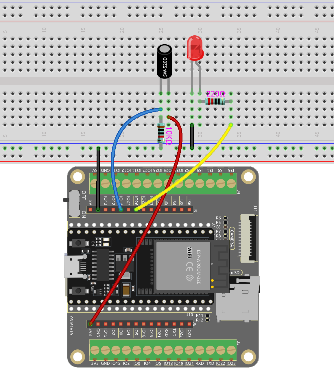
Wiring
Code
Note
You can open the file
5.2_tilt_switch.inounder the path ofesp32-starter-kit-main\c\codes\5.2_tilt_switch.After selecting the board (ESP32 Dev Module) and the appropriate port, click the Upload button.
After code upload successfully, the LED will be turned on when the switch is upright, and turned off when the switch is tilted.