Note
Hello, welcome to the SunFounder Raspberry Pi & Arduino & ESP32 Enthusiasts Community on Facebook! Dive deeper into Raspberry Pi, Arduino, and ESP32 with fellow enthusiasts.
Why Join?
Expert Support: Solve post-sale issues and technical challenges with help from our community and team.
Learn & Share: Exchange tips and tutorials to enhance your skills.
Exclusive Previews: Get early access to new product announcements and sneak peeks.
Special Discounts: Enjoy exclusive discounts on our newest products.
Festive Promotions and Giveaways: Take part in giveaways and holiday promotions.
👉 Ready to explore and create with us? Click [here] and join today!
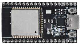
ESP32 Board
The ESP32 is a powerful and versatile microcontroller featuring dual-core processing, built-in Wi-Fi and Bluetooth, and extensive peripheral support. Its low-power design makes it well suited for compact and high-performance IoT applications.
Key features include:
Processing Power: It’s equipped with a dual-core Xtensa® 32-bit LX6 microprocessor, offering scalability and flexibility.
Wireless Capabilities: With integrated 2.4 GHz Wi-Fi and dual-mode Bluetooth, it’s perfectly suited for applications demanding stable wireless communication.
Memory & Storage: It comes with ample SRAM and high-performance flash storage, catering to user programs and data storage needs.
GPIO: Offering up to 38 GPIO pins, it supports a variety of external devices and sensors.
Low Power Consumption: Multiple power-saving modes are available, making it ideal for battery-powered or energy-efficient scenarios.
Security: Integrated encryption and security features ensure user data and privacy are well-protected.
Versatility: From simple household appliances to complex industrial machinery, the board delivers consistent, efficient performance.
In summary, the ESP32 board not only offers robust processing capabilities and diverse connectivity options but also boasts an array of features making it a preferred choice in the IoT and smart device sectors.
Pinout Diagram
The ESP32 has some pin usage limitations due to various functionalities sharing certain pins. When designing a project, it’s a good practice to carefully plan the pin usage and cross-check for potential conflicts to ensure proper functioning and avoid issues.
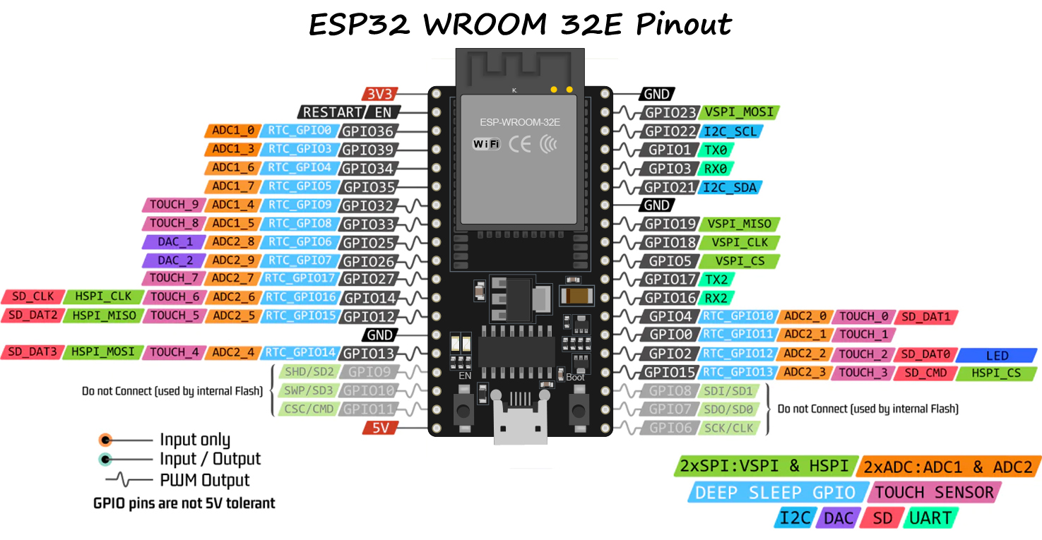
Here are some of the key restrictions and considerations:
ADC1 and ADC2: ADC2 cannot be used when WiFi or Bluetooth is active. However, ADC1 can be used without any restrictions.
Bootstrapping Pins: GPIO0, GPIO2, GPIO5, GPIO12, and GPIO15 are used for bootstrapping during the boot process. Care should be taken not to connect external components that could interfere with the boot process on these pins.
JTAG Pins: GPIO12, GPIO13, GPIO14, and GPIO15 can be used as JTAG pins for debugging purposes. If JTAG debugging is not required, these pins can be used as regular GPIOs.
Touch Pins: Some pins support touch functionalities. These pins should be used carefully if you intend to use them for touch sensing.
Power Pins: Some pins are reserved for power-related functions and should be used accordingly. For example, avoid drawing excessive current from power supply pins like 3V3 and GND.
Input-only Pins: Some pins are input-only and should not be used as outputs.
Strapping Pins
ESP32 has five strapping pins:
Strapping Pins |
Description |
|---|---|
IO5 |
Defaults to pull-up, the voltage level of IO5 and IO15 affects the Timing of SDIO Slave. |
IO0 |
Defaults to pull-up, if pulled low, it enters download mode. |
IO2 |
Defaults to pull-down, IO0 and IO2 will make ESP32 enter download mode. |
IO12(MTDI) |
Defaults to pull-down, if pulled high, ESP32 will fail to boot up normally. |
IO15(MTDO) |
Defaults to pull-up, if pulled low, debug log will not be visible. Additionally, the voltage level of IO5 and IO15 affects the Timing of SDIO Slave. |
Software can read the values of these five bits from register “GPIO_STRAPPING”. During the chip’s system reset release (power-on-reset, RTC watchdog reset and brownout reset), the latches of the strapping pins sample the voltage level as strapping bits of “0” or “1”, and hold these bits until the chip is powered down or shut down. The strapping bits configure the device’s boot mode, the operating voltage of VDD_SDIO and other initial system settings.
Each strapping pin is connected to its internal pull-up/pull-down during the chip reset. Consequently, if a strapping pin is unconnected or the connected external circuit is high-impedance, the internal weak pull-up/pull-down will determine the default input level of the strapping pins.
To change the strapping bit values, users can apply the external pull-down/pull-up resistances, or use the host MCU’s GPIOs to control the voltage level of these pins when powering on ESP32.
After reset release, the strapping pins work as normal-function pins. Refer to following table for a detailed boot-mode configuration by strapping pins.
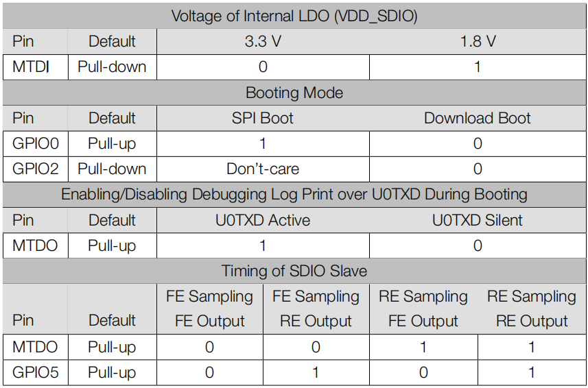
FE: falling-edge, RE: rising-edge
Firmware can configure register bits to change the settings of “Voltage of Internal LDO (VDD_SDIO)” and “Timing of SDIO Slave”, after booting.
The module integrates a 3.3 V SPI flash, so the pin MTDI cannot be set to 1 when the module is powered up.
ESP32 Camera Extension
We have designed an expansion board that enables you to fully utilize the camera and SD card functionalities of the ESP32 board. By combining the OV2640 camera, Micro SD, and ESP32 board, you get an all-in-one expansion board.
The board provides two types of GPIO headers - one with female headers, perfect for quick prototyping projects. The other type features screw terminals, ensuring stable wire connections and making it suitable for IoT projects.
Additionally, you can power your project using a Power Pack. If the Power Pack runs low, you can conveniently charge it by simply plugging in a 5V USB cable. This makes it a great tool for outdoor projects and remote applications.
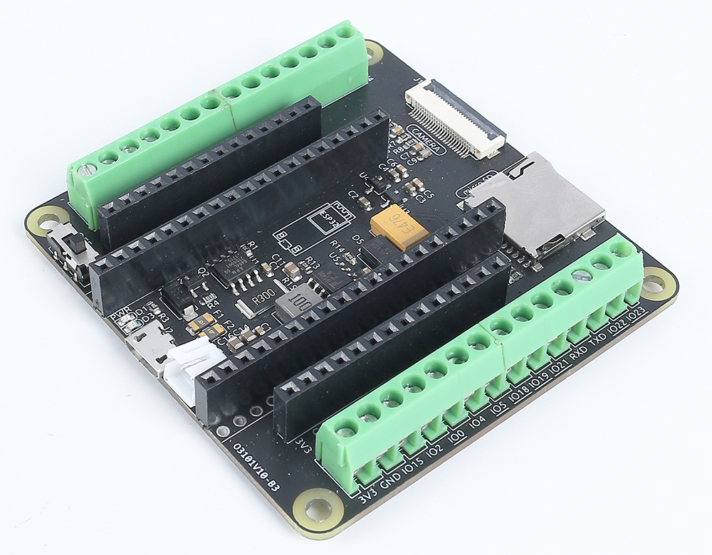
Interface Introduction
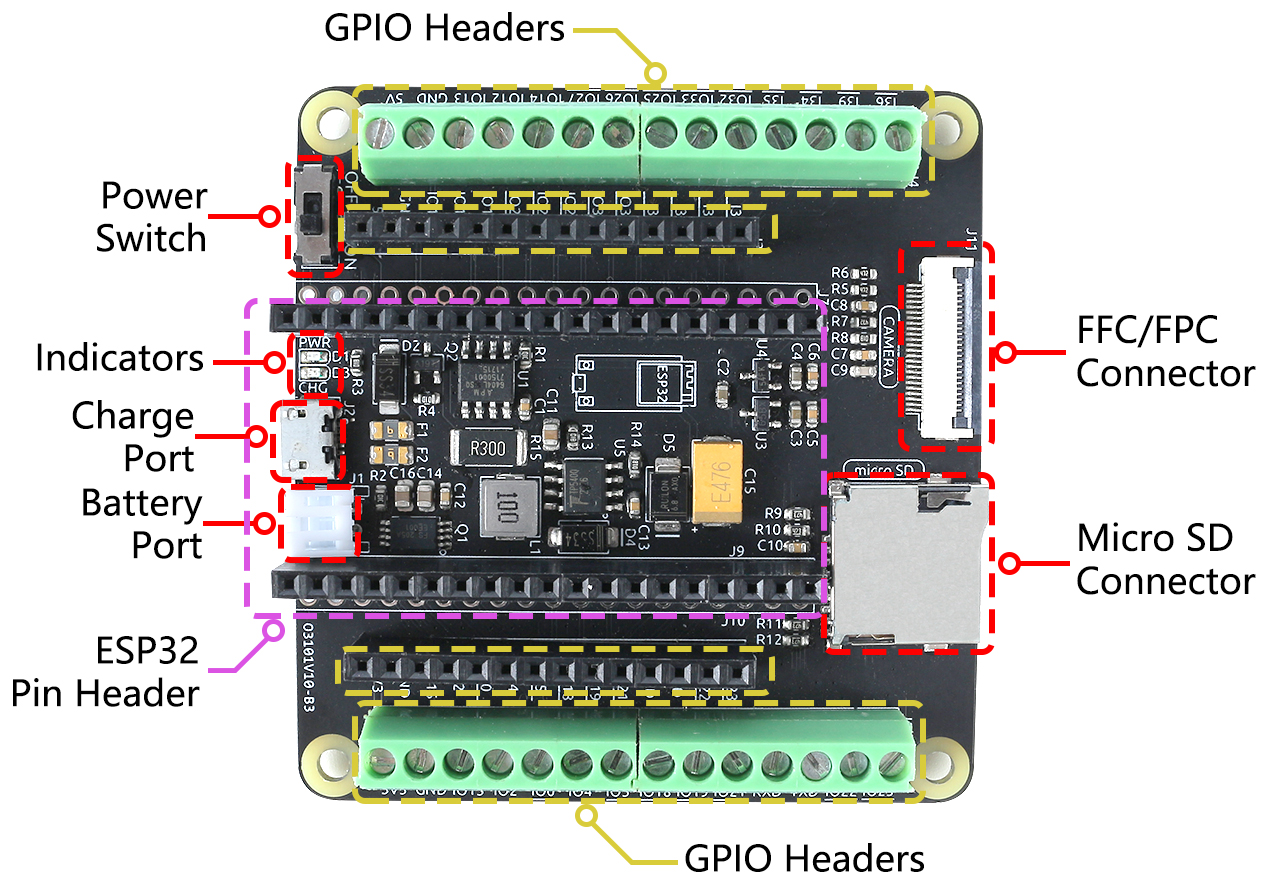
- Power Switch
Controls the Power Pack’s power supply, toggling it on and off.
- Charging Port
Upon connecting a 5V USB cable, the Power Pack can be charged.
- Power Pack Port
Features a PH2.0-2P interface, compatible with Power Pack.
Provides power to both the ESP32 board and ESP32 Camera Extension.
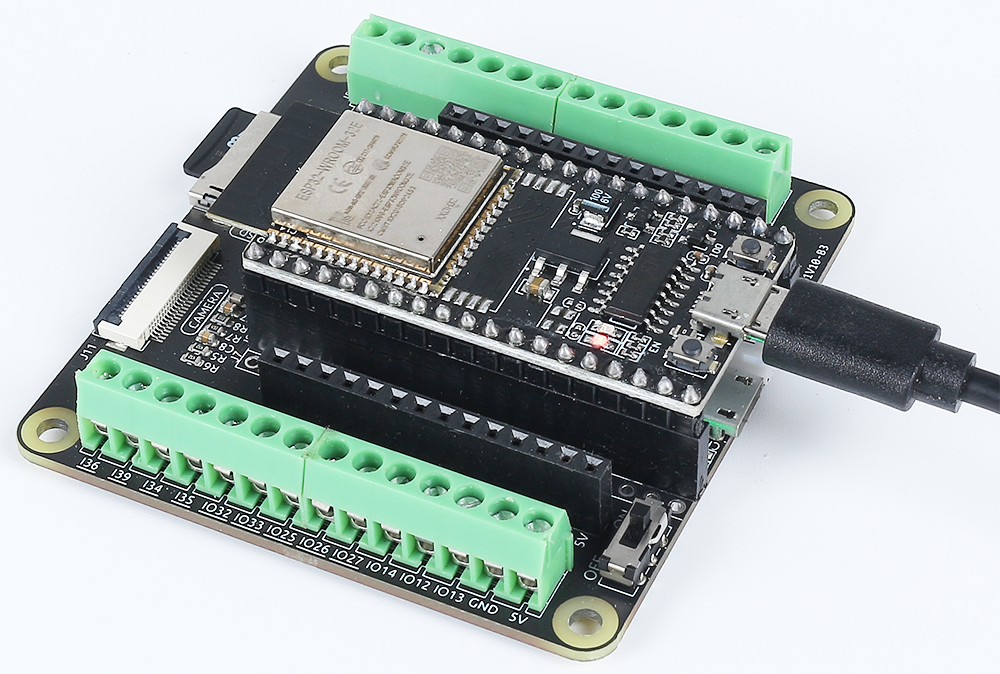
- ESP32 Pin Headers
Intended for the ESP32 board module. Pay close attention to its orientation; ensure both USB ports face the same side to avoid incorrect placement.
- GPIO Headers
Female Headers: Used to connect various components to the ESP32, perfect for quick prototyping projects.
Screw Terminal: 3.5mm pitch 14pin screw terminal, ensuring stable wire connections and making it suitable for IoT projects.
- Indicator Lights
PWR: Lights up when the Power Pack is powered or when a USB cable is directly plugged into the ESP32.
CHG: Illuminates upon connecting a USB cable to the board’s charging port, signifying charging onset. It will turn off once the Power Pack is fully charged.
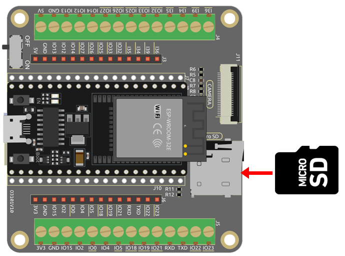
- Micro SD Connector
Spring-loaded slot for the easy insertion and ejection of Micro SD card.
- 24-pin 0.5mm FFC / FPC connector
Designed for the OV2640 camera, making it suitable for various vision-related projects.
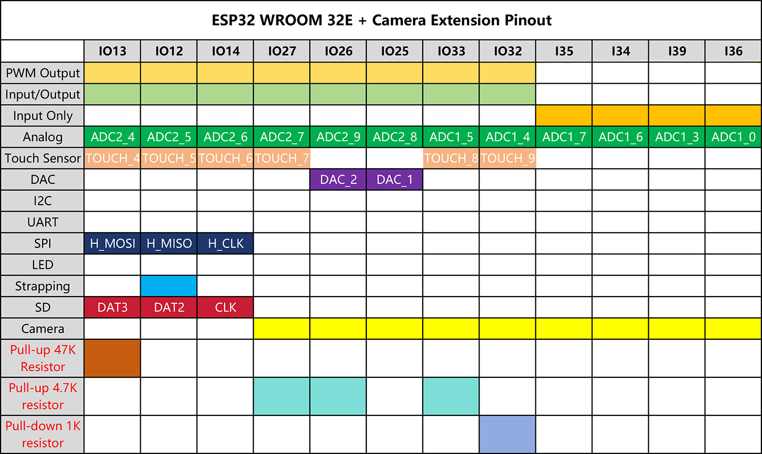
ESP32 Camera Extension Pinout
The ESP32 board’s pinout diagram can be found in Pinout Diagram.
However, when the ESP32 board is inserted into the extension board, some of its pins may also be used to drive the Micro SD card or a camera.
Consequently, pull-up or pull-down resistors have be added to these pins. If you’re using these pins as inputs, it’s crucial to account for these resistors as they can affect input levels.
Here’s the pinout table for the right-side pins:
Here’s the pinout table for the left-side pins:
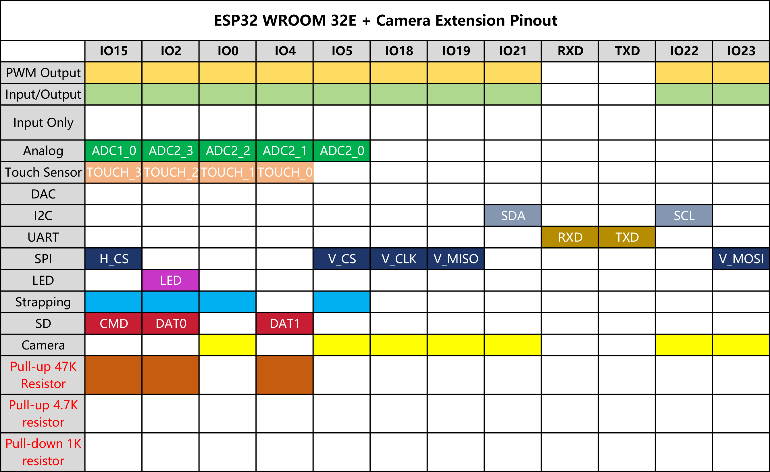
Note
There are some specific constraints:
IO33 is connected to a 4.7K pull-up resistor and a filtering capacitor, which prevents it from driving the WS2812 RGB Strip.
Interface Insertion Guide
Upload Code
When you need to upload code to the ESP32 board, connect it to your computer using a USB cable.
Inserting the Micro SD Card
Gently push in the Micro SD card to secure it in place. Pushing it again will eject it.
Attaching the Camera
When connecting the camera, ensure the black stripe of the FPC cable is facing upwards and is fully inserted into the connector.