Note
Hello, welcome to the SunFounder Raspberry Pi & Arduino & ESP32 Enthusiasts Community on Facebook! Dive deeper into Raspberry Pi, Arduino, and ESP32 with fellow enthusiasts.
Why Join?
Expert Support: Solve post-sale issues and technical challenges with help from our community and team.
Learn & Share: Exchange tips and tutorials to enhance your skills.
Exclusive Previews: Get early access to new product announcements and sneak peeks.
Special Discounts: Enjoy exclusive discounts on our newest products.
Festive Promotions and Giveaways: Take part in giveaways and holiday promotions.
👉 Ready to explore and create with us? Click [here] and join today!
4.3 Swinging Servo
A Servo is a type of position-based device known for its ability to maintain specific angles and deliver precise rotation. This makes it highly desirable for control systems that demand consistent angle adjustments. It’s not surprising that Servos have found extensive use in high-end remote-controlled toys, from airplane models to submarine replicas and sophisticated remote-controlled robots.
In this intriguing adventure, we’ll challenge ourselves to manipulate the Servo in a unique way - by making it sway! This project offers a brilliant opportunity to dive deeper into the dynamics of Servos, sharpening your skills in precise control systems and offering a deeper understanding of their operation.
Are you ready to make the Servo dance to your tunes? Let’s embark on this exciting journey!
Required Components
In this project, we need the following components.
It’s definitely convenient to buy a whole kit, here’s the link:
Name |
ITEMS IN THIS KIT |
LINK |
|---|---|---|
ESP32 Starter Kit |
320+ |
You can also buy them separately from the links below.
COMPONENT INTRODUCTION |
PURCHASE LINK |
|---|---|
Available Pins
Here is a list of available pins on the ESP32 board for this project.
Available Pins |
IO13, IO12, IO14, IO27, IO26, IO25, IO33, IO32, IO15, IO2, IO0, IO4, IO5, IO18, IO19, IO21, IO22, IO23 |
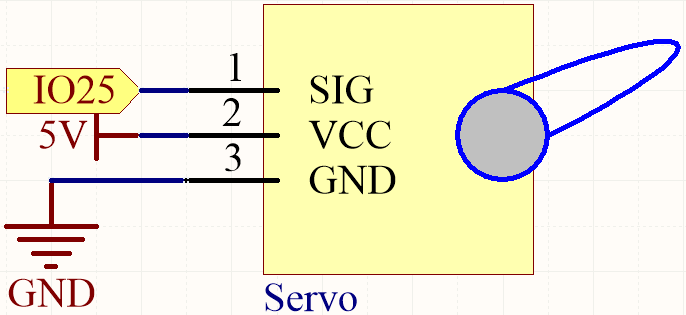
Schematic
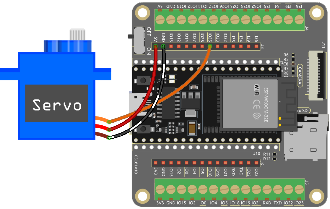
Wiring
Orange wire is signal and connected to IO25.
Red wire is VCC and connected to 5V.
Brown wire is GND and connected to GND.
Code
Note
Open the
4.3_servo.inofile under the path ofesp32-starter-kit-main\c\codes\4.3_servo. Or copy this code into Arduino IDE.After selecting the board (ESP32 Dev Module) and the appropriate port, click the Upload button.
The
ESP32Servolibrary is used here, you can install it from the Library Manager.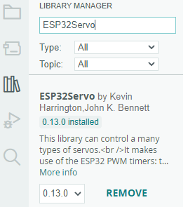
Once you finish uploading the code, you can see the servo arm rotating in the range 0°~180°.
How it works?
Include the ESP32Servo library: This line imports the ESP32Servo library, which is required to control the servo motor.
#include <ESP32Servo.h>
Define the servo and the pin it is connected to: This section declares a Servo object (
myServo) and a constant integer (servoPin) to represent the pin that the servo motor is connected to (pin 25).// Define the servo and the pin it is connected to Servo myServo; const int servoPin = 25;
Define the minimum and maximum pulse widths for the servo: This section sets the minimum and maximum pulse widths for the servo motor (0.5 ms and 2.5 ms, respectively).
// Define the minimum and maximum pulse widths for the servo
const int minPulseWidth = 500; // 0.5 ms
const int maxPulseWidth = 2500; // 2.5 ms
The
setupfunction initializes the servo motor by attaching it to the specified pin and setting its pulse width range. It also sets the PWM frequency for the servo to the standard 50Hz.void setup() { // Attach the servo to the specified pin and set its pulse width range myServo.attach(servoPin, minPulseWidth, maxPulseWidth); // Set the PWM frequency for the servo myServo.setPeriodHertz(50); // Standard 50Hz servo }
attach (int pin, int min, int max): This function attaches the servo motor to the specified GPIO pin and sets the minimum and maximum pulse widths for the servo.pin: The GPIO pin number that the servo is connected to.The
minandmax: the minimum and maximum pulse widths, respectively, in microseconds. These values define the range of motion of the servo motor.
setPeriodHertz(int hertz): This function sets the PWM frequency for the servo motor in hertz.hertz: The desired PWM frequency in hertz. The default PWM frequency for servos is 50Hz, which is suitable for most applications.
The
loopfunction is the main part of the code that continuously runs. It rotates the servo motor from 0 to 180 degrees, then back to 0 degrees. This is done by mapping the angle to the corresponding pulse width and updating the servo motor with the new pulse width value.void loop() { // Rotate the servo from 0 to 180 degrees for (int angle = 0; angle <= 180; angle++) { int pulseWidth = map(angle, 0, 180, minPulseWidth, maxPulseWidth); myServo.writeMicroseconds(pulseWidth); delay(15); } // Rotate the servo from 180 to 0 degrees for (int angle = 180; angle >= 0; angle--) { int pulseWidth = map(angle, 0, 180, minPulseWidth, maxPulseWidth); myServo.writeMicroseconds(pulseWidth); delay(15); } }
writeMicroseconds(int value): This function sets the pulse width of the servo motor in microseconds.value: The desired pulse width in microseconds.
The
writeMicroseconds(int value)function takes an integer value as its argument, representing the desired pulse width in microseconds. This value should typically fall within the range specified by the minimum and maximum pulse widths (minPulseWidthandmaxPulseWidth) defined earlier in the code. The function then sets the pulse width for the servo motor, causing it to move to the corresponding position.