Note
Hello, welcome to the SunFounder Raspberry Pi & Arduino & ESP32 Enthusiasts Community on Facebook! Dive deeper into Raspberry Pi, Arduino, and ESP32 with fellow enthusiasts.
Why Join?
Expert Support: Solve post-sale issues and technical challenges with help from our community and team.
Learn & Share: Exchange tips and tutorials to enhance your skills.
Exclusive Previews: Get early access to new product announcements and sneak peeks.
Special Discounts: Enjoy exclusive discounts on our newest products.
Festive Promotions and Giveaways: Take part in giveaways and holiday promotions.
👉 Ready to explore and create with us? Click [here] and join today!
7.6 Take Photo SD
This document describes a project that involves taking a photo using the ESP32-CAM and saving it to an SD card. The aim of the project is to provide a simple solution for capturing images using the ESP32-CAM and storing them on an SD card.
Required Components
In this project, we need the following components.
It’s definitely convenient to buy a whole kit, here’s the link:
Name |
ITEMS IN THIS KIT |
LINK |
|---|---|---|
ESP32 Starter Kit |
320+ |
You can also buy them separately from the links below.
COMPONENT INTRODUCTION |
PURCHASE LINK |
|---|---|
Note
The ESP32 camera you received may have either a short FPC cable or a 75mm FPC cable. Regardless of the type, both function identically.
Related Precautions
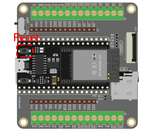
When using the ESP32-CAM, it is important to note that the GPIO 0 pin must be connected to GND to upload a sketch. Additionally, after connecting GPIO 0 to GND, the ESP32-CAM onboard RESET button must be pressed to put the board in flashing mode. It is also important to ensure that the SD card is properly mounted before saving images to it.
Operating Steps
Insert your SD card into the computer using a card reader, and then format it. You can refer to the tutorial at How to format the SD card?.
Then, remove the card reader and insert the SD card into the expansion board.
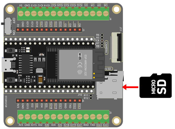
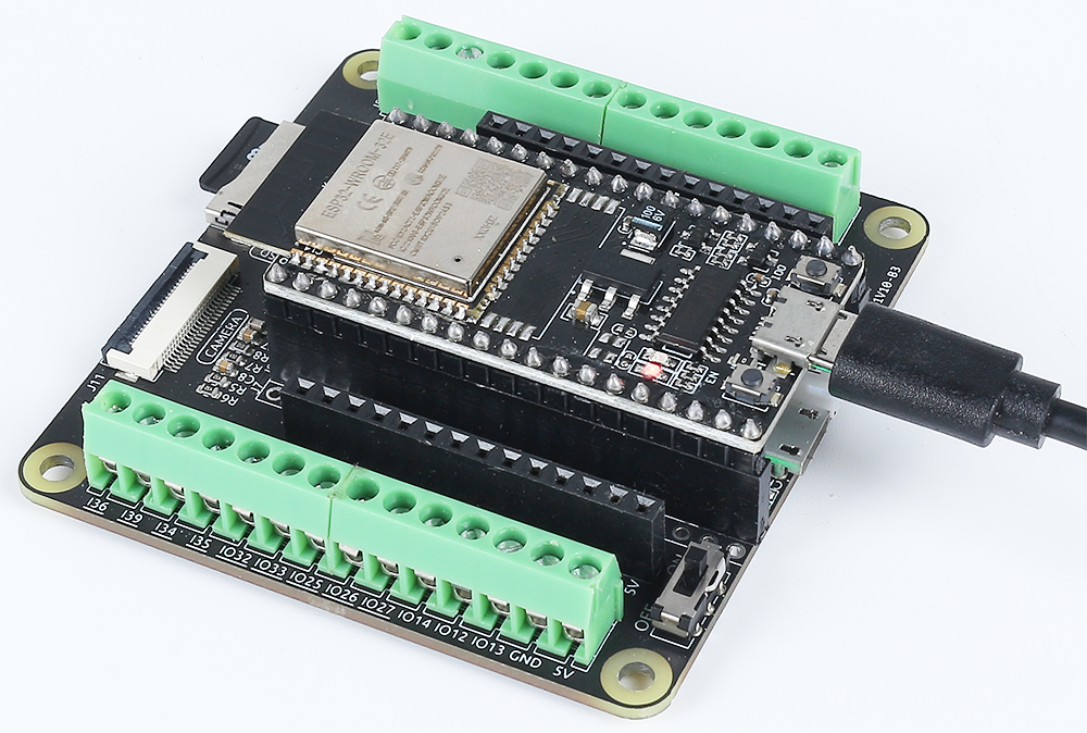
Now, plug in the camera.
Connect ESP32 board to the computer using the USB cable.
Open the code.
Note
Open the
7.6_take_photo_sd.inofile under the path ofesp32-starter-kit-main\c\codes\7.6_take_photo_sd.After selecting the board (ESP32 Dev Module) and the appropriate port, click the Upload button.
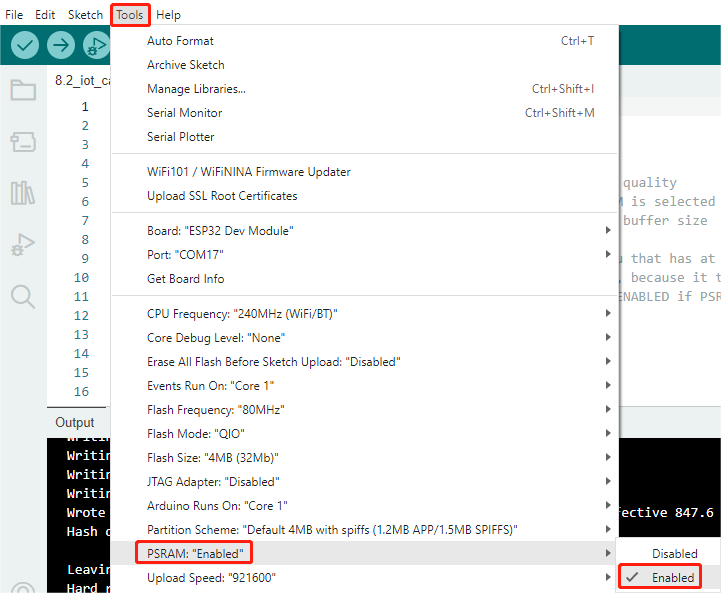
Now, enable PSRAM.
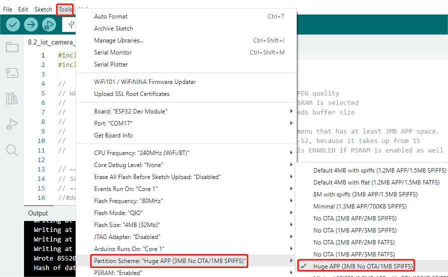
Set the partition scheme to Huge APP (3MB No OTA/1MB SPIFFS).
Select the appropriate port and board in the Arduino IDE and upload the code to your ESP32.
After the successful upload of the code, press the Reset button to take a photo. Additionally, you can check the Serial Monitor to see the following information indicating the successful capture.
Picture file name: /picture9.jpg
Saved file to path: /picture9.jpg
Going to sleep now
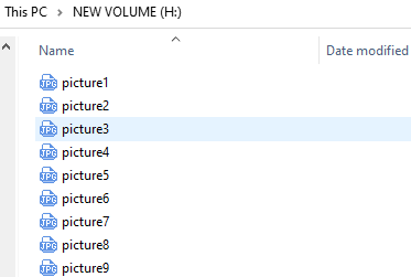
Now, remove the SD card from the expansion board and insert it into your computer. You will be able to view the photos you just took.
How it works?
This code operates an AI Thinker ESP32-CAM to take a photo, save it to an SD card, and then put the ESP32-CAM into deep sleep. Here is a breakdown of the key parts:
Libraries: The code starts with the inclusion of the necessary libraries for the ESP32-CAM, file system (FS), SD card, and EEPROM (used for storing data across power cycles).
#include "esp_camera.h"
#include "Arduino.h"
#include "FS.h"                // SD Card ESP32
#include "SD_MMC.h"            // SD Card ESP32
#include "soc/soc.h"           // Disable brownour problems
#include "soc/rtc_cntl_reg.h"  // Disable brownour problems
#include "driver/rtc_io.h"
#include <EEPROM.h>  // read and write from flash memory
Pin Definitions: This section sets up constants that represent the ESP32-CAM’s pin connections to the camera module.
#define PWDN_GPIO_NUM 32
#define RESET_GPIO_NUM -1
#define XCLK_GPIO_NUM 0
#define SIOD_GPIO_NUM 26
#define SIOC_GPIO_NUM 27

#define Y9_GPIO_NUM 35
#define Y8_GPIO_NUM 34
#define Y7_GPIO_NUM 39
#define Y6_GPIO_NUM 36
#define Y5_GPIO_NUM 21
#define Y4_GPIO_NUM 19
#define Y3_GPIO_NUM 18
#define Y2_GPIO_NUM 5
#define VSYNC_GPIO_NUM 25
#define HREF_GPIO_NUM 23
#define PCLK_GPIO_NUM 22
Global Variables: A global variable
pictureNumberis declared to keep track of the number of pictures taken and saved to the SD card.int pictureNumber = 0;
Setup Function: In the
setup()function, several tasks are accomplished:First, the brown-out detector is disabled to prevent the ESP32-CAM from resetting during high current draws (like when the camera is operating).
WRITE_PERI_REG(RTC_CNTL_BROWN_OUT_REG, 0); //disable brownout detector
The Serial communication is initialized for debugging.
Serial.begin(115200);
The camera configuration is set up with
camera_config_t, including the GPIO pins, XCLK frequency, pixel format, frame size, jpeg quality, and framebuffer count.camera_config_t config; config.ledc_channel = LEDC_CHANNEL_0; config.ledc_timer = LEDC_TIMER_0; config.pin_d0 = Y2_GPIO_NUM; config.pin_d1 = Y3_GPIO_NUM; config.pin_d2 = Y4_GPIO_NUM; config.pin_d3 = Y5_GPIO_NUM; config.pin_d4 = Y6_GPIO_NUM; config.pin_d5 = Y7_GPIO_NUM; config.pin_d6 = Y8_GPIO_NUM; config.pin_d7 = Y9_GPIO_NUM; config.pin_xclk = XCLK_GPIO_NUM; config.pin_pclk = PCLK_GPIO_NUM; config.pin_vsync = VSYNC_GPIO_NUM; config.pin_href = HREF_GPIO_NUM; config.pin_sscb_sda = SIOD_GPIO_NUM; config.pin_sscb_scl = SIOC_GPIO_NUM; config.pin_pwdn = PWDN_GPIO_NUM; config.pin_reset = RESET_GPIO_NUM; config.xclk_freq_hz = 20000000; config.pixel_format = PIXFORMAT_JPEG;
The camera is then initialized with the configuration, and if it fails, an error message is printed.
esp_err_t err = esp_camera_init(&config);
if (err != ESP_OK) {
    Serial.printf("Camera init failed with error 0x%x", err);
    return;
}
The SD card is initialized, and if it fails, an error message is printed.
if (!SD_MMC.begin()) {
    Serial.println("SD Card Mount Failed");
    return;
}

uint8_t cardType = SD_MMC.cardType();
if (cardType == CARD_NONE) {
    Serial.println("No SD Card attached");
    return;
}
A photo is captured with the camera and stored in the framebuffer.
fb = esp_camera_fb_get();
if (!fb) {
    Serial.println("Camera capture failed");
    return;
}
The EEPROM is read to retrieve the number of the last picture, then the picture number for the new photo is incremented.
EEPROM.begin(EEPROM_SIZE);
pictureNumber = EEPROM.read(0) + 1;
A path for the new picture is created on the SD card, with a filename corresponding to the picture number.
String path = "/picture" + String(pictureNumber) + ".jpg";

fs::FS &fs = SD_MMC;
Serial.printf("Picture file name: %s\n", path.c_str());
After saving the photo, the picture number is stored back into EEPROM for retrieval in the next power cycle.
File file = fs.open(path.c_str(), FILE_WRITE);
if (!file) {
    Serial.println("Failed to open file in writing mode");
} else {
    file.write(fb->buf, fb->len);  // payload (image), payload length
    Serial.printf("Saved file to path: %s\n", path.c_str());
    EEPROM.write(0, pictureNumber);
    EEPROM.commit();
}
file.close();
esp_camera_fb_return(fb);
Finally, the onboard LED (flash) is turned off and the ESP32-CAM goes into deep sleep.
pinMode(4, OUTPUT);
digitalWrite(4, LOW);
rtc_gpio_hold_en(GPIO_NUM_4);
Sleep Mode: The ESP32-CAM goes into deep sleep after taking each photo to conserve power. It can be woken up by a reset or by a signal on specific pins.
delay(2000);
Serial.println("Going to sleep now");
delay(2000);
esp_deep_sleep_start();
Serial.println("This will never be printed");
Loop Function: The
loop()function is empty because after the setup process, the ESP32-CAM immediately goes into deep sleep.
Note that for this code to work, you need to ensure that GPIO 0 is connected to GND when uploading the sketch, and you might have to press the on-board RESET button to put your board into flashing mode. Also, remember to replace “/picture” with your own file name. The size of the EEPROM is set to 1, which means it can store values from 0 to 255. If you plan to take more than 255 pictures, you’ll need to increase the EEPROM size and adjust how you store and read the pictureNumber.