Note
Hello, welcome to the SunFounder Raspberry Pi & Arduino & ESP32 Enthusiasts Community on Facebook! Dive deeper into Raspberry Pi, Arduino, and ESP32 with fellow enthusiasts.
Why Join?
Expert Support: Solve post-sale issues and technical challenges with help from our community and team.
Learn & Share: Exchange tips and tutorials to enhance your skills.
Exclusive Previews: Get early access to new product announcements and sneak peeks.
Special Discounts: Enjoy exclusive discounts on our newest products.
Festive Promotions and Giveaways: Take part in giveaways and holiday promotions.
👉 Ready to explore and create with us? Click [here] and join today!
8.9 Blynk-based Intrusion Notification System
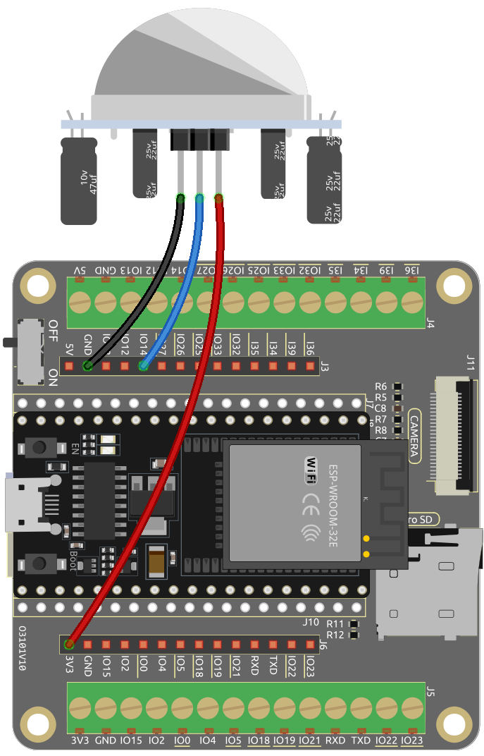
This project demonstrate a simple home intrusion detection system using a PIR motion sensor (HC-SR501). When the system is set to “Away” mode through the Blynk app, the PIR sensor monitors for motion. Any detected movement triggers a notification on the Blynk app, alerting the user of potential intrusion.
Required Components
In this project, we need the following components.
It’s definitely convenient to buy a whole kit, here’s the link:
Name |
ITEMS IN THIS KIT |
LINK |
|---|---|---|
ESP32 Starter Kit |
320+ |
You can also buy them separately from the links below.
COMPONENT INTRODUCTION |
PURCHASE LINK |
|---|---|
1. Circuit Assembly
2. Blynk Configuration
2.1 Initializing Blynk
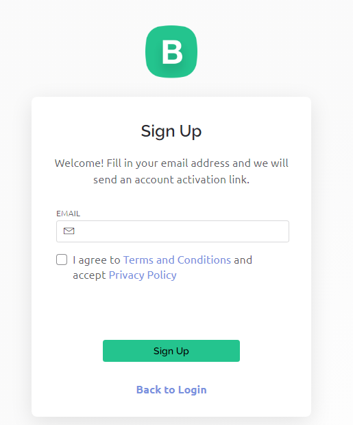
Go to the BLYNK page and select Sign Up FREE or Enterprise Solution.

Enter your email to start the registration process.
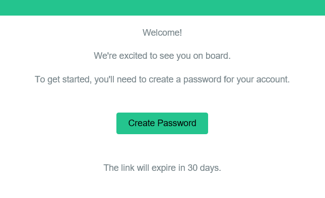
Check your email for a prompt, and click on the Create Password link in the email to set your password.
After confirmation, a Blynk Tour will begin where you can quickly learn about some of Blynk’s key features.

After completing the Blynk Tour, a window will pop up where you can choose to Explore Blueprints or click Quick Start to quickly connect your device. However, in this case, we will select “Have a look around first”.

2.2 Template Creation
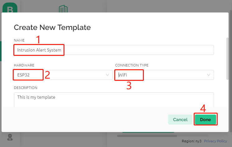
Start by creating a template in Blynk. Follow the steps to set up the Intrusion Alert System template.
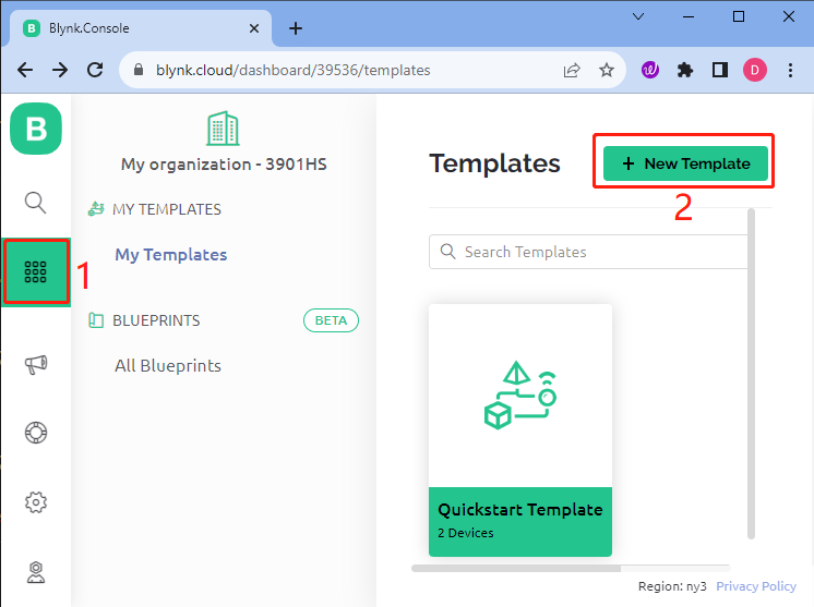
Name your template, choose ESP32 as the Hardware, select WiFi as the Connection Type, and then click Done.
Enter the template, where you’ll be prompted with next steps. Click Configure template to upload a cover image, enhance the description, and more. Follow the remaining three steps to complete the setup.

2.3 Set Up Datastreams
Open the newly created template and go to the datastream setup page.
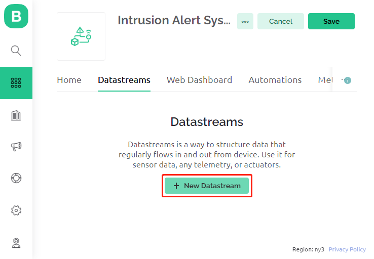
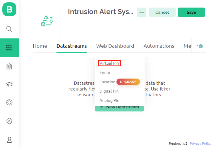
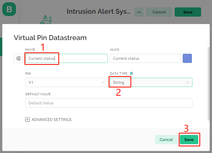
Click New Datastream, and in the popup, select Virtual Pin.
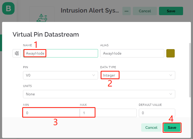
Name the Virtual Pin V0 as AwayMode and set the DATA TYPE to Integer, with MIN and MAX values as 0 and 1.
Similarly, create another Virtual Pin named Current Status and set the DATA TYPE to String.
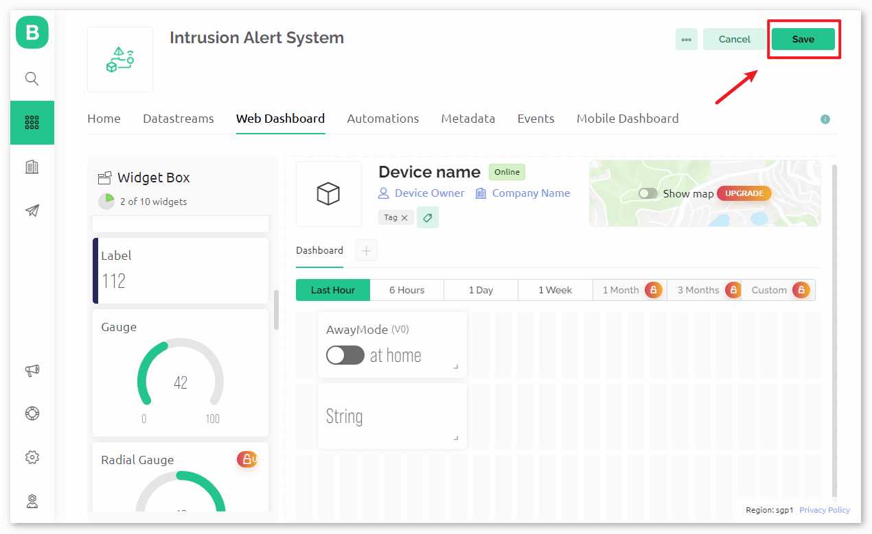
2.4 Set up the Web Dashboard
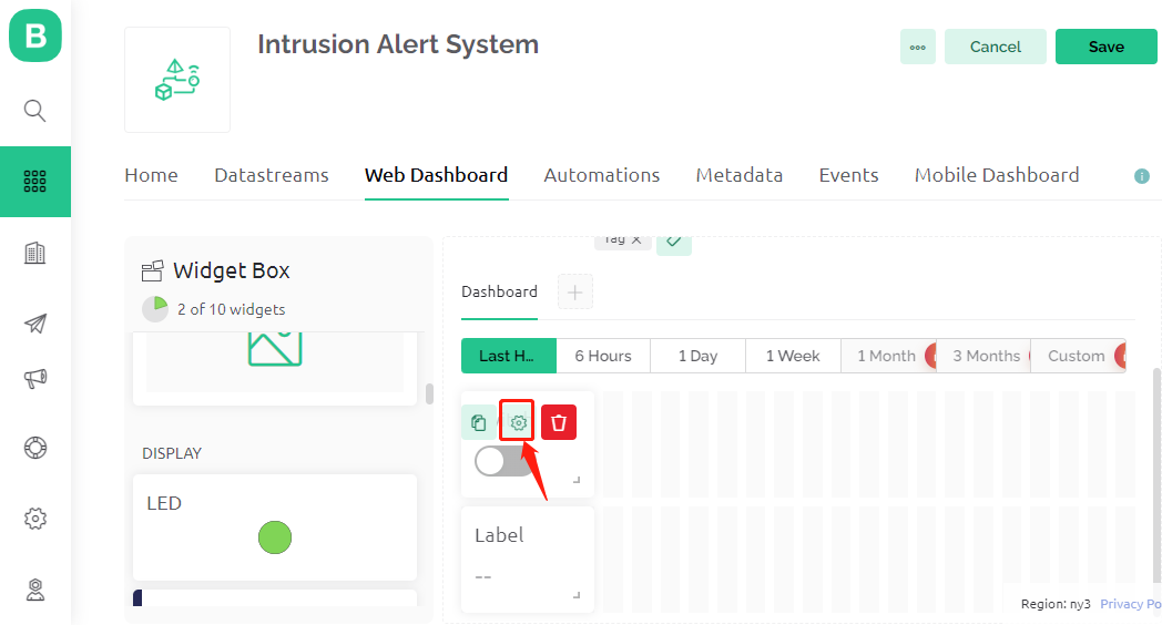
Drag and drop both the Switch widget and the Label widget onto the Web Dashboard.
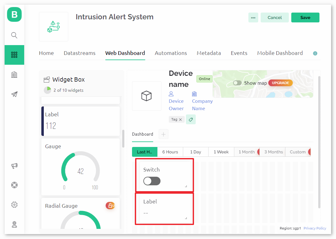
Hover over a widget to see three icons. Use the Settings icon to configure the widget’s properties.
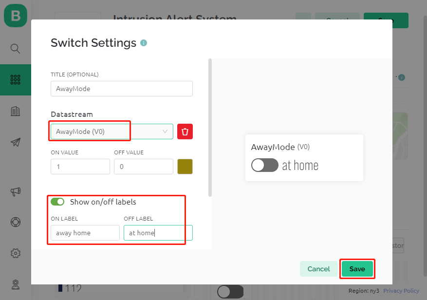
Configure the Switch widget to link with the AwayMode(V0) datastream, setting the ONLABEL and OFFLABEL to display “away home” and “at home”, respectively.
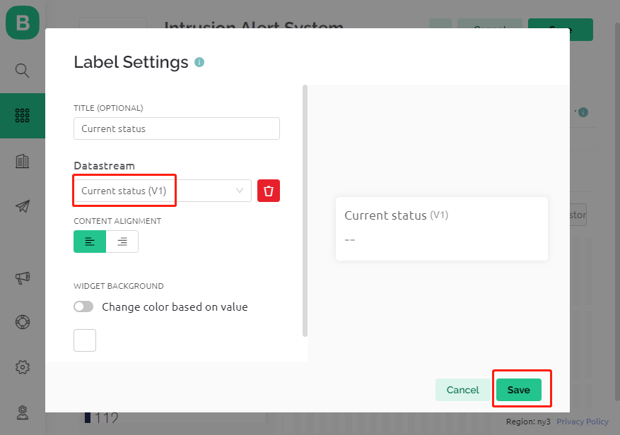
In the Label widget settings, link it to the Current Status(V1) datastream.
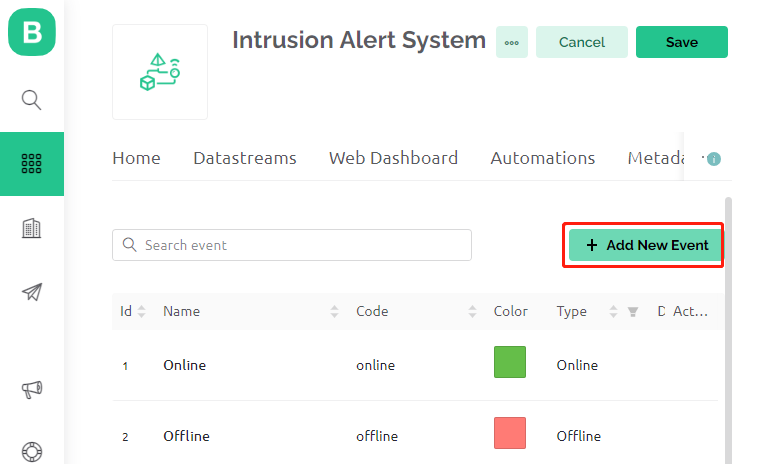
2.5 Setting Up an Event
Click Events & Notifications and then Create Event.
Name the event and specify its code. Choose Warning for TYPE and provide a short description for the notification email. Adjust notification frequency as desired.
Note
Ensure the EVENT CODE is set as
intrusion_detected. Any changes here require corresponding code adjustments.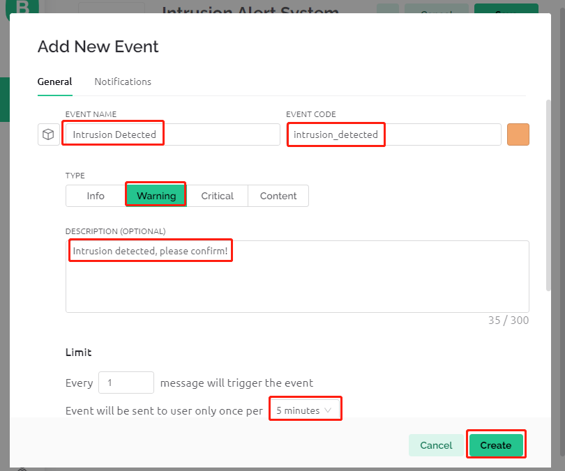
Go to the Notifications section to enable notifications and configure email settings.
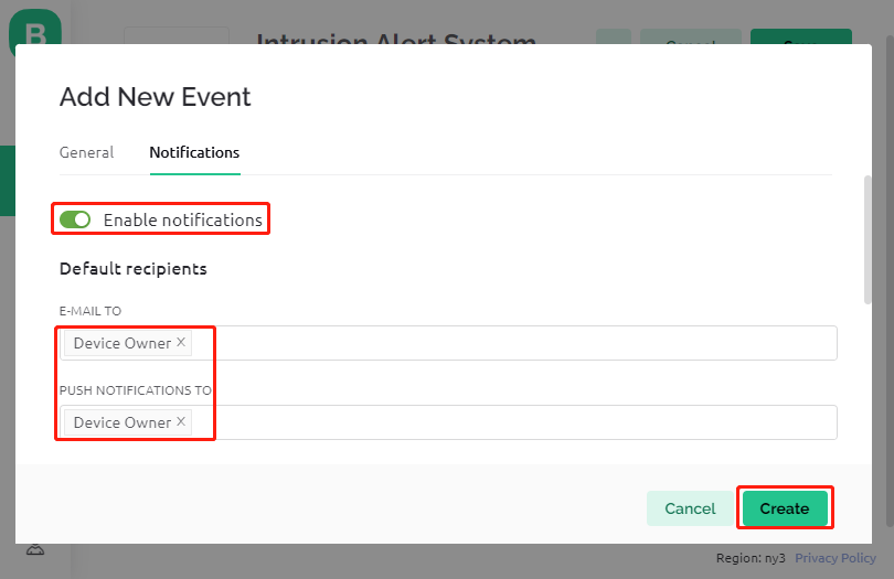
Under Settings, define how frequently an event triggers notifications and set intervals according to your preference. Remember to click Create to save your settings.

2.6 Saving the Template
Remember to save your changes to the template.
2.7 Making a Device
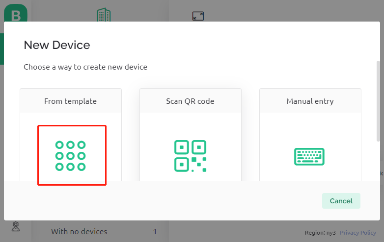
It’s time to create a new device from the template.
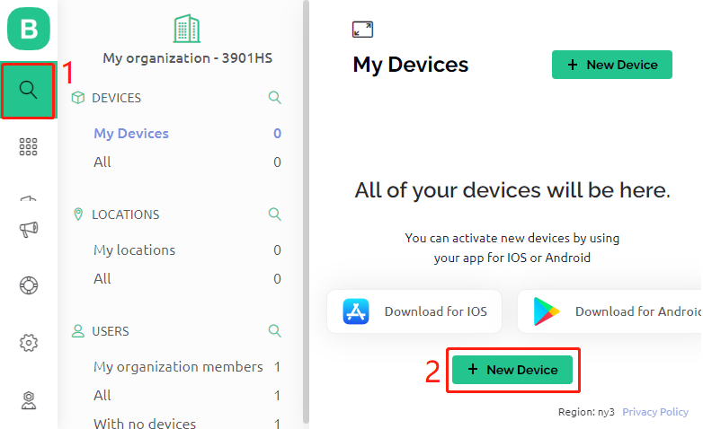
Select From template to begin.
Choose the Intrusion Alert System template and click Create.
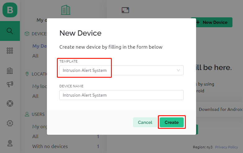
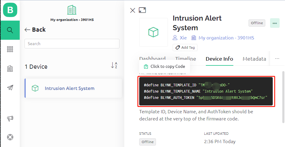
Note down the Template ID, Device Name, and AuthToken for your ESP32 integration.
3. Code Execution
Before running the code, make sure to install the
Blynklibrary from the Library Manager on the Arduino IDE.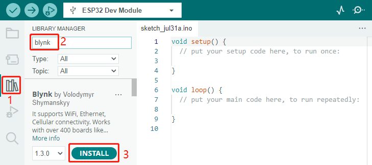
Open the
iot_9_intrusion_alert_system.inofile, which is located in theesp32-starter-kit-main\c\codes\iot_9_intrusion_alert_systemdirectory. You can also copy its content into the Arduino IDE.Replace the placeholders for
BLYNK_TEMPLATE_ID,BLYNK_TEMPLATE_NAME, andBLYNK_AUTH_TOKENwith your own unique IDs.#define BLYNK_TEMPLATE_ID "TMPxxxxxxx" #define BLYNK_TEMPLATE_NAME "Intrusion Alert System" #define BLYNK_AUTH_TOKEN "xxxxxxxxxxxxx"
You also need to enter your WiFi network’s
ssidandpassword.char ssid[] = "your_ssid"; char pass[] = "your_password";
Choose the correct board (ESP32 Dev Module) and port, then click the Upload button.
Open the Serial monitor (set baud rate to 115200) and wait for a successful connection message.
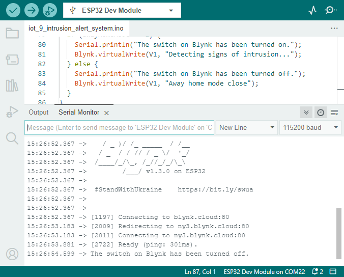
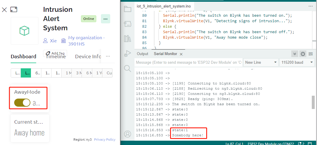
After a successful connection, activating the switch in Blynk will start the PIR module’s surveillance. When motion is detected (state of 1), it will say, “Somebody here!” and send an alert to your email.
4. Code explanation
Configuration & Libraries
Here, you set up the Blynk constants and credentials. You also include the necessary libraries for the ESP32 and Blynk.
/* Comment this out to disable prints and save space */ #define BLYNK_PRINT Serial #define BLYNK_TEMPLATE_ID "xxxxxxxxxxx" #define BLYNK_TEMPLATE_NAME "Intrusion Alert System" #define BLYNK_AUTH_TOKEN "xxxxxxxxxxxxxxxxxxxxxxxxxxx" #include <WiFi.h> #include <WiFiClient.h> #include <BlynkSimpleEsp32.h>
WiFi Setup
Enter your WiFi credentials.
char ssid[] = "your_ssid";
char pass[] = "your_password";
PIR Sensor Configuration
Set the pin where the PIR sensor is connected and initialize the state variables.
const int sensorPin = 14;
int state = 0;
int awayHomeMode = 0;
BlynkTimer timer;
setup() Function
This function initializes the PIR sensor as an input, sets up serial communication, connects to WiFi, and configures Blynk.
We use
timer.setInterval(1000L, myTimerEvent)to set the timer interval insetup(), here we set to execute themyTimerEvent()function every 1000ms. You can modify the first parameter oftimer.setInterval(1000L, myTimerEvent)to change the interval betweenmyTimerEventexecutions.
void setup() {

    pinMode(sensorPin, INPUT);  // Set PIR sensor pin as input
    Serial.begin(115200);           // Start serial communication at 115200 baud rate for debugging

    // Configure Blynk and connect to WiFi
    Blynk.begin(BLYNK_AUTH_TOKEN, ssid, pass);

    timer.setInterval(1000L, myTimerEvent);  // Setup a function to be called every second
}
loop() Function
The loop function continuously runs Blynk and the Blynk timer functions.
void loop() {
   Blynk.run();
   timer.run();
}
Blynk App Interaction
These functions are called when the device connects to Blynk and when there’s a change in the state of the virtual pin V0 on the Blynk app.
Every time the device connects to the Blynk server, or reconnects due to poor network conditions, the
BLYNK_CONNECTED()function is called. TheBlynk.syncVirtual()command request a single Virtual Pin value. The specified Virtual Pin will performBLYNK_WRITE()call.Whenever the value of a virtual pin on the BLYNK server changes, it will trigger
BLYNK_WRITE().
// This function is called every time the device is connected to the Blynk.Cloud
BLYNK_CONNECTED() {
    Blynk.syncVirtual(V0);
}

// This function is called every time the Virtual Pin 0 state changes
BLYNK_WRITE(V0) {
    awayHomeMode = param.asInt();
    // additional logic
}
Data Handling
Every second, the
myTimerEvent()function callssendData(). If the away mode is enabled on Blynk, it checks the PIR sensor and sends a notification to Blynk if motion is detected.We use
Blynk.virtualWrite(V1, "Somebody in your house! Please check!");to change the text of a label.Use
Blynk.logEvent("intrusion_detected");to log event to Blynk.
void myTimerEvent() {
   sendData();
}

void sendData() {
   if (awayHomeMode == 1) {
      state = digitalRead(sensorPin);  // Read the state of the PIR sensor

      Serial.print("state:");
      Serial.println(state);

      // If the sensor detects movement, send an alert to the Blynk app
      if (state == HIGH) {
        Serial.println("Somebody here!");
        Blynk.virtualWrite(V1, "Somebody in your house! Please check!");
        Blynk.logEvent("intrusion_detected");
      }
   }
}
Reference