Note
Hello, welcome to the SunFounder Raspberry Pi & Arduino & ESP32 Enthusiasts Community on Facebook! Dive deeper into Raspberry Pi, Arduino, and ESP32 with fellow enthusiasts.
Why Join?
Expert Support: Solve post-sale issues and technical challenges with help from our community and team.
Learn & Share: Exchange tips and tutorials to enhance your skills.
Exclusive Previews: Get early access to new product announcements and sneak peeks.
Special Discounts: Enjoy exclusive discounts on our newest products.
Festive Promotions and Giveaways: Take part in giveaways and holiday promotions.
👉 Ready to explore and create with us? Click [here] and join today!
5.10 Thermometer
A thermistor is a temperature sensor that exhibits a strong dependence on temperature, and it can be classified into two types: Negative Temperature Coefficient (NTC) and Positive Temperature Coefficient (PTC). The resistance of an NTC thermistor decreases with increasing temperature, while the resistance of a PTC thermistor increases with increasing temperature.
In this project, we will be using an NTC thermistor. By connecting the NTC thermistor to an analog input pin of the ESP32 microcontroller, we can measure its resistance, which is directly proportional to the temperature.
By incorporating the NTC thermistor and performing the necessary calculations, we can accurately measure the temperature and display it on the I2C LCD1602 module. This project enables real-time temperature monitoring and provides a visual interface for temperature display.
Required Components
In this project, we need the following components.
It’s definitely convenient to buy a whole kit, here’s the link:
Name |
ITEMS IN THIS KIT |
LINK |
|---|---|---|
ESP32 Starter Kit |
320+ |
You can also buy them separately from the links below.
COMPONENT INTRODUCTION |
PURCHASE LINK |
|---|---|
Available Pins
Available Pins
Here is a list of available pins on the ESP32 board for this project.
Available Pins
IO14, IO25, I35, I34, I39, I36
Strapping Pins
The following pins are strapping pins, which affect the startup process of the ESP32 during power on or reset. However, once the ESP32 is booted up successfully, they can be used as regular pins.
Strapping Pins
IO0, IO12
Schematic
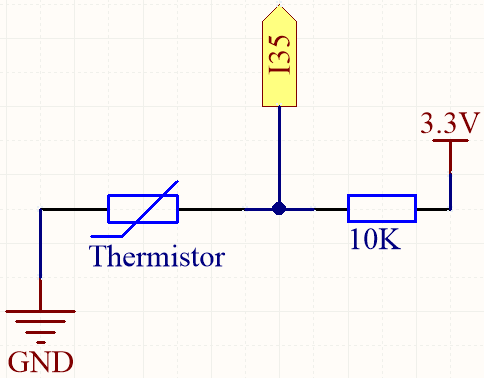
When the temperature rises, the resistance of the thermistor decreases, causing the value read on I35 to decrease. Additionally, by using a formula, you can convert the analog value into temperature and then print it out.
Wiring
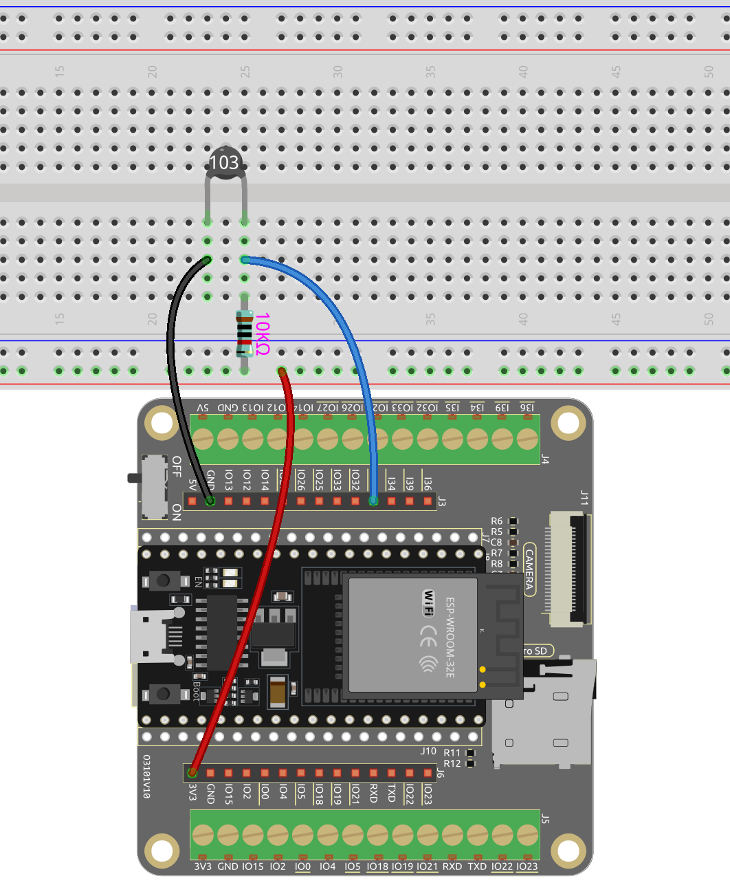
Note
The thermistor is black and marked 103.
The color ring of the 10K ohm resistor is red, black, black, red and brown.
Code
Note
Open the
5.10_thermistor.inofile under the path ofesp32-starter-kit-main\c\codes\5.10_thermistor.After selecting the board (ESP32 Dev Module) and the appropriate port, click the Upload button.
After the code is successfully uploaded, the Serial Monitor will print out the Celsius and Fahrenheit temperatures.
How it works?
Each thermistor has a normal resistance. Here it is 10k ohm, which is measured under 25 degree Celsius.
When the temperature gets higher, the resistance of the thermistor decreases. Then the voltage data is converted to digital quantities by the A/D adapter.
The temperature in Celsius or Fahrenheit is output via programming.
Here is the relation between the resistance and temperature:
RT =RN expB(1/TK - 1/TN)
RT is the resistance of the NTC thermistor when the temperature is TK.
RN is the resistance of the NTC thermistor under the rated temperature TN. Here, the numerical value of RN is 10k.
TK is a Kelvin temperature and the unit is K. Here, the numerical value of TK is
273.15 + degree Celsius.TN is a rated Kelvin temperature; the unit is K too. Here, the numerical value of TN is
273.15+25.And B(beta), the material constant of NTC thermistor, is also called heat sensitivity index with a numerical value
3950.exp is the abbreviation of exponential, and the base number
eis a natural number and equals 2.7 approximately.Convert this formula
TK=1/(ln(RT/RN)/B+1/TN)to get Kelvin temperature that minus 273.15 equals degree Celsius.This relation is an empirical formula. It is accurate only when the temperature and resistance are within the effective range.
Learn More
You can also display the calculated Celsius and Fahrenheit temperatures on the I2C LCD1602.
Note
You can open the file
5.10_thermistor_lcd.inounder the path ofeuler-kit/arduino/5.10_thermistor_lcd.After selecting the board (ESP32 Dev Module) and the appropriate port, click the Upload button.
The
LiquidCrystal I2Clibrary is used here, you can install it from the Library Manager.