Note
Hello, welcome to the SunFounder Raspberry Pi & Arduino & ESP32 Enthusiasts Community on Facebook! Dive deeper into Raspberry Pi, Arduino, and ESP32 with fellow enthusiasts.
Why Join?
Expert Support: Solve post-sale issues and technical challenges with help from our community and team.
Learn & Share: Exchange tips and tutorials to enhance your skills.
Exclusive Previews: Get early access to new product announcements and sneak peeks.
Special Discounts: Enjoy exclusive discounts on our newest products.
Festive Promotions and Giveaways: Take part in giveaways and holiday promotions.
👉 Ready to explore and create with us? Click [here] and join today!
5.8 Turn the Knob
A potentiometer is a three-terminal device that is commonly used to adjust the resistance in a circuit. It features a knob or a sliding lever that can be used to vary the resistance value of the potentiometer. In this project, we will utilize it to control the brightness of an LED, similar to a desk lamp in our daily life. By adjusting the position of the potentiometer, we can change the resistance in the circuit, thereby regulating the current flowing through the LED and adjusting its brightness accordingly. This allows us to create a customizable and adjustable lighting experience, similar to that of a desk lamp.
Required Components
In this project, we need the following components.
It’s definitely convenient to buy a whole kit, here’s the link:
Name |
ITEMS IN THIS KIT |
LINK |
|---|---|---|
ESP32 Starter Kit |
320+ |
You can also buy them separately from the links below.
COMPONENT INTRODUCTION |
PURCHASE LINK |
|---|---|
Available Pins
Available Pins
Here is a list of available pins on the ESP32 board for this project.
Available Pins
IO14, IO25, I35, I34, I39, I36
Strapping Pins
The following pins are strapping pins, which affect the startup process of the ESP32 during power on or reset. However, once the ESP32 is booted up successfully, they can be used as regular pins.
Strapping Pins
IO0, IO12
Schematic
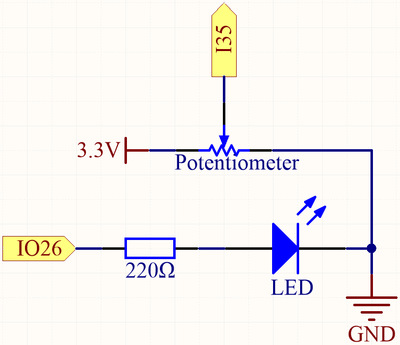
When you rotate the potentiometer, the value of I35 will change. By programming, you can use the value of I35 to control the brightness of the LED. Therefore, as you rotate the potentiometer, the brightness of the LED will also change accordingly.
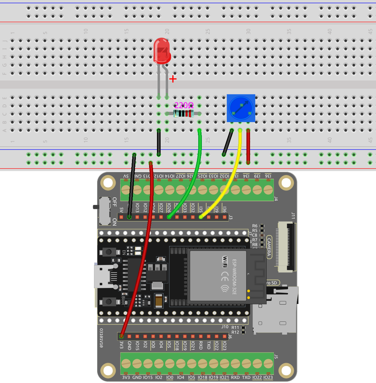
Wiring
Code
Note
You can open the file
5.8_pot.inounder the path ofesp32-starter-kit-main\c\codes\5.8_pot.After selecting the board (ESP32 Dev Module) and the appropriate port, click the Upload button.
After the code is uploaded successfully, rotate the potentiometer and you will see the brightness of the LED change accordingly. At the same time you can see the analog and voltage values of the potentiometer in the serial monitor.
How it works?
Define constants for pin connections and PWM settings.
const int potPin = 35; // Potentiometer connected to
const int ledPin = 26; // LED connected to

// PWM settings
const int freq = 5000; // PWM frequency
const int resolution = 12; // PWM resolution (bits)
Here the PWM resolution is set to 12 bits and the range is 0-4095.
Configure the system in the
setup()function.void setup() { Serial.begin(115200); // Configure PWM ledcAttach(ledPin, freq, resolution); }
In the
setup()function, the Serial communication is started at a baud rate of 115200.The
ledcAttach()function is called to set up the specified LED pin with the specified frequency and resolution.
Main loop (executed repeatedly) in the loop() function.
void loop() {

    int potValue = analogRead(potPin); // read the value of the potentiometer
    uint32_t voltage_mV = analogReadMilliVolts(potPin); // Read the voltage in millivolts

    ledcWrite(ledPin, potValue);

    Serial.print("Potentiometer Value: ");
    Serial.print(potValue);
    Serial.print(", Voltage: ");
    Serial.print(voltage_mV / 1000.0); // Convert millivolts to volts
    Serial.println(" V");

    delay(100);
}
uint32_t analogReadMilliVolts(uint8_t pin);: This function is used to get ADC value for a given pin/ADC channel in millivolts.pinGPIO pin to read analog value.
The potentiometer value is directly used as the PWM duty cycle for controlling the LED brightness via the
ledcWrite()function, as the range of values is also from 0 to 4095.