Note
Hello, welcome to the SunFounder Raspberry Pi & Arduino & ESP32 Enthusiasts Community on Facebook! Dive deeper into Raspberry Pi, Arduino, and ESP32 with fellow enthusiasts.
Why Join?
Expert Support: Solve post-sale issues and technical challenges with help from our community and team.
Learn & Share: Exchange tips and tutorials to enhance your skills.
Exclusive Previews: Get early access to new product announcements and sneak peeks.
Special Discounts: Enjoy exclusive discounts on our newest products.
Festive Promotions and Giveaways: Take part in giveaways and holiday promotions.
👉 Ready to explore and create with us? Click [here] and join today!
2.2 Fading
In the previous project, we controlled the LED by turning it on and off using digital output. In this project, we will create a breathing effect on the LED by utilizing Pulse Width Modulation (PWM). PWM is a technique that allows us to control the brightness of an LED or the speed of a motor by varying the duty cycle of a square wave signal.
With PWM, instead of simply turning the LED on or off, we will be adjusting the amount of time the LED is on versus the amount of time it is off within each cycle. By rapidly switching the LED on and off at varying intervals, we can create the illusion of the LED gradually brightening and dimming, simulating a breathing effect.
By using the PWM capabilities of the ESP32 board, we can achieve smooth and precise control over the LED’s brightness. This breathing effect adds a dynamic and visually appealing element to your projects, creating an eye-catching display or ambiance.
Required Components
In this project, we need the following components.
It’s definitely convenient to buy a whole kit, here’s the link:
Name |
ITEMS IN THIS KIT |
LINK |
|---|---|---|
ESP32 Starter Kit |
320+ |
You can also buy them separately from the links below.
COMPONENT INTRODUCTION |
PURCHASE LINK |
|---|---|
Available Pins
Here is a list of available pins on the ESP32 board for this project.
Available Pins |
IO13, IO12, IO14, IO27, IO26, IO25, IO33, IO32, IO15, IO2, IO0, IO4, IO5, IO18, IO19, IO21, IO22, IO23 |
Schematic
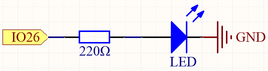
This project is the same circuit as the first project 2.1 Hello, LED!, but the signal type is different. The first project is to output digital high and low levels (0&1) directly from pin26 to make the LED light up or turn off, this project is to output PWM signal from pin26 to control the brightness of the LED.
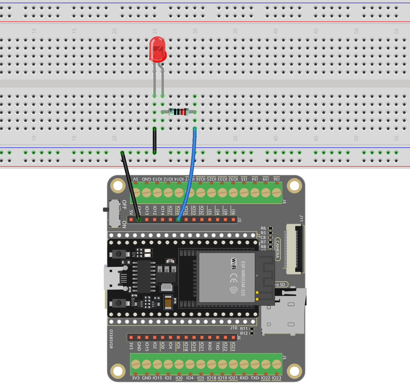
Wiring
Code
Note
You can open the file
2.2_fading_led.inounder the path ofesp32-starter-kit-main\c\codes\2.2_fading_led.After selecting the board (ESP32 Dev Module) and the appropriate port, click the Upload button.
After the code is uploaded successfully, you can see the LED breathing.
How it works?
Define constants and variables。
const int ledPin = 26; // The GPIO pin for the LED
int brightness = 0;
int fadeAmount = 5;
ledPin: The GPIO pin number where the LED is connected (in this case, GPIO 26).brightness: The current brightness level of the LED (initially set to 0).fadeAmount: The amount by which the LED’s brightness will change in each step (set to 5).
Initializes the PWM channel and configures the LED pin.
void setup() {
  ledcAttach(ledPin, 5000, 8);  // Attach the LED pin
}
Here we use the LEDC (LED control) peripheral which is primarly designed to control the intensity of LEDs, although it can also be used to generate PWM signals for other purposes.
bool ledcAttach(uint8_t pin, uint32_t freq, uint8_t resolution);: This function is used to setup LEDC pin with given frequency and resolution. LEDC channel will be selected automatically.pinselect GPIO pin.freqselect frequency of pwm.resolution_bitsselect resolution for ledc channel. Range is 1-14 bits (1-20 bits for ESP32).
The
loop()function contains the main logic of the program and runs continuously. It updates the LED’s brightness, inverts the fade amount when the brightness reaches the minimum or maximum value, and introduces a delay.void loop() { ledcWrite(ledPin, brightness); // Write the new brightness value to the PWM pin brightness = brightness + fadeAmount; if (brightness <= 0 || brightness >= 255) { fadeAmount = -fadeAmount; } delay(50); // Wait for 50 milliseconds }
bool ledcWrite(uint8_t pin, uint32_t duty);: This function is used to set duty for the LEDC pin.pinselect LEDC pin.dutyselect duty to be set for selected channel.