Note
Hello, welcome to the SunFounder Raspberry Pi & Arduino & ESP32 Enthusiasts Community on Facebook! Dive deeper into Raspberry Pi, Arduino, and ESP32 with fellow enthusiasts.
Why Join?
Expert Support: Solve post-sale issues and technical challenges with help from our community and team.
Learn & Share: Exchange tips and tutorials to enhance your skills.
Exclusive Previews: Get early access to new product announcements and sneak peeks.
Special Discounts: Enjoy exclusive discounts on our newest products.
Festive Promotions and Giveaways: Take part in giveaways and holiday promotions.
👉 Ready to explore and create with us? Click [here] and join today!
8.10 Android Application - RGB LED Operation via Arduino and Bluetooth
The objective of this project is to develop an Android application capable of manipulating the hue of an RGB LED through a smartphone using Bluetooth technology.
This Android application will be constructed utilizing a complimentary web-based platform known as MIT App Inventor 2. The project presents an excellent opportunity to gain familiarity with the interfacing of an Arduino with a smartphone.
Required Components
In this project, we need the following components.
It’s definitely convenient to buy a whole kit, here’s the link:
Name |
ITEMS IN THIS KIT |
LINK |
|---|---|---|
ESP32 Starter Kit |
320+ |
You can also buy them separately from the links below.
COMPONENT INTRODUCTION |
PURCHASE LINK |
|---|---|
1. Creation of the Android Application
The Android application will be fashioned using a free web application known as MIT App Inventor. MIT App Inventor serves as an excellent starting point for Android development, owing to its intuitive drag-and-drop features allowing for the creation of simplistic applications.
Now, let’s begin.
Here is the login page: http://ai2.appinventor.mit.edu. You will require a Google account to register with MIT App Inventor.
After logging in, navigate to Projects -> Import project (.aia) from my computer. Subsequently, upload the
control_rgb_led.aiafile located in the pathesp32-starter-kit-main\c\codes\iot_10_bluetooth_app_inventor.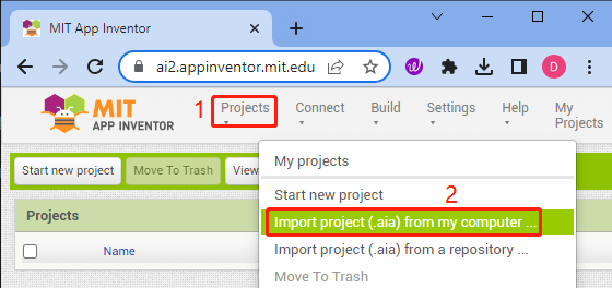
Upon uploading the
.aiafile, you will see the application on the MIT App Inventor software. This is a pre-configured template. You can modify this template after you have familiarized yourself with MIT App Inventor through the following steps.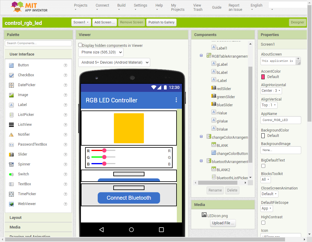
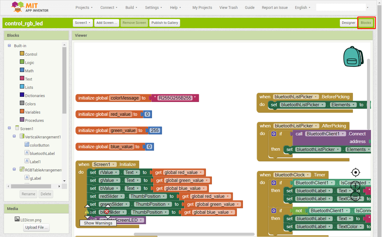
In MIT App Inventor, you have 2 primary sections: the Designer and the Blocks.
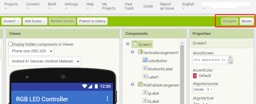
The Designer allows you to add buttons, text, screens, and modify the overall aesthetic of your application.
Subsequently, you have the Blocks section. The Blocks section facilitates the creation of bespoke functions for your application.
To install the application on a smartphone, navigate to the Build tab.
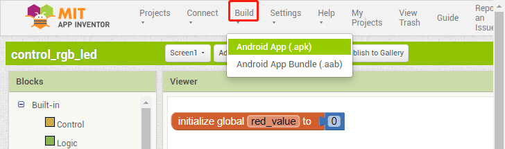
You can generate a
.apkfile. After selecting this option, a page will appear allowing you to choose between downloading a.apkfile or scanning a QR code for installation. Follow the installation guide to complete the application installation.If you wish to upload this app to Google Play or another app marketplace, you can generate a
.aabfile.
2. Upload the code
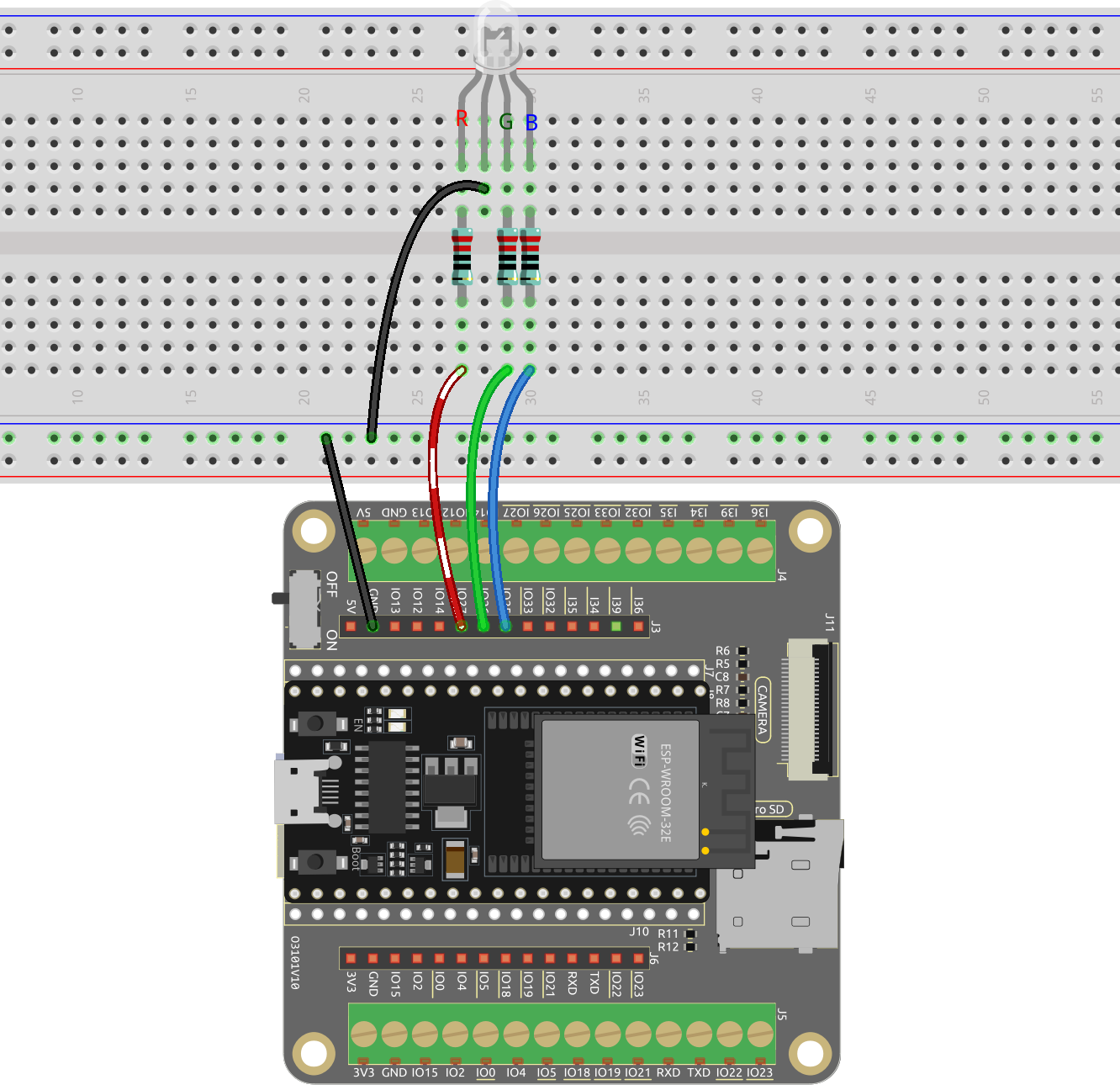
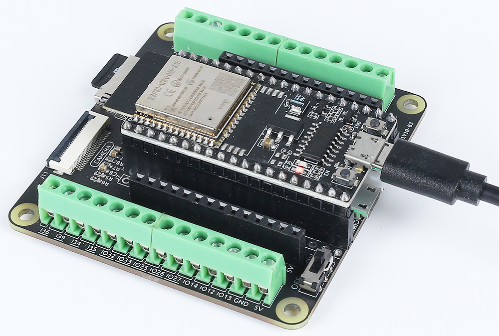
Build the circuit.
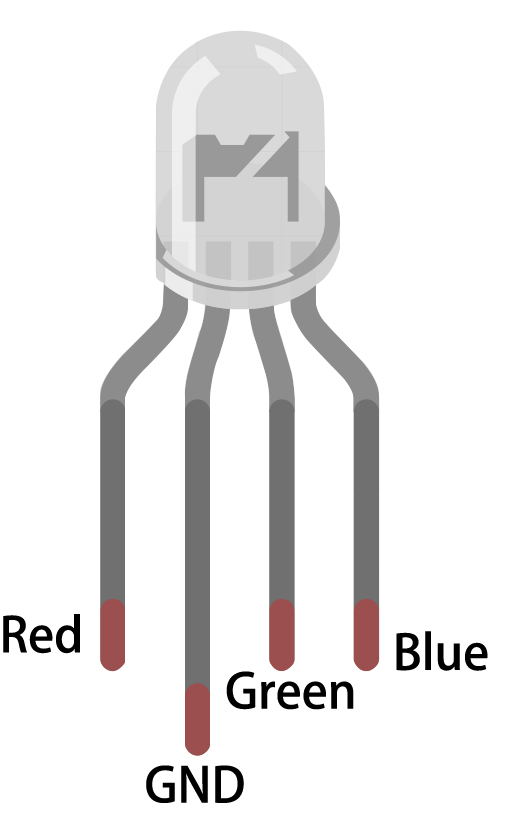
The RGB LED comprises 4 pins: the elongated pin is the common cathode pin, typically connected to GND; the pin to the left of the longest pin represents Red; and the two pins on the right symbolize Green and Blue.
Subsequently, connect the ESP32 board to your computer using a USB cable.
Open the
iot_10_bluetooth_app_inventor.inofile situated in theesp32-starter-kit-main\c\codes\iot_10_bluetooth_app_inventordirectory, or copy the code into the Arduino IDE.Upon selecting the appropriate board (ESP32 Dev Module) and port, click the Upload button.
3. App and ESP32 Connection
Ensure that the application created earlier is installed on your smartphone.
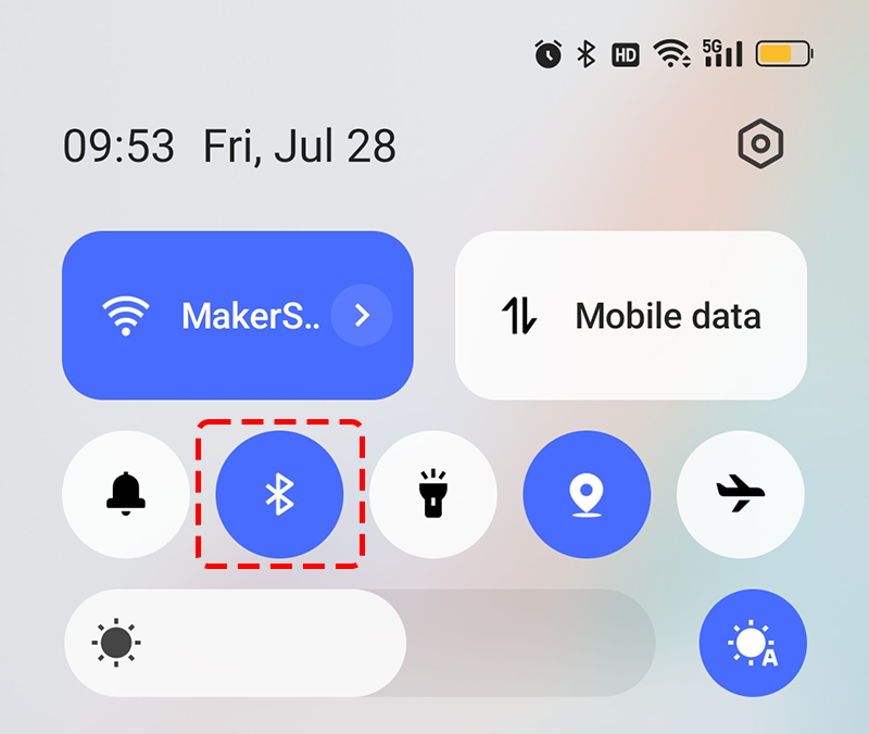
Initially, activate Bluetooth on your smartphone.
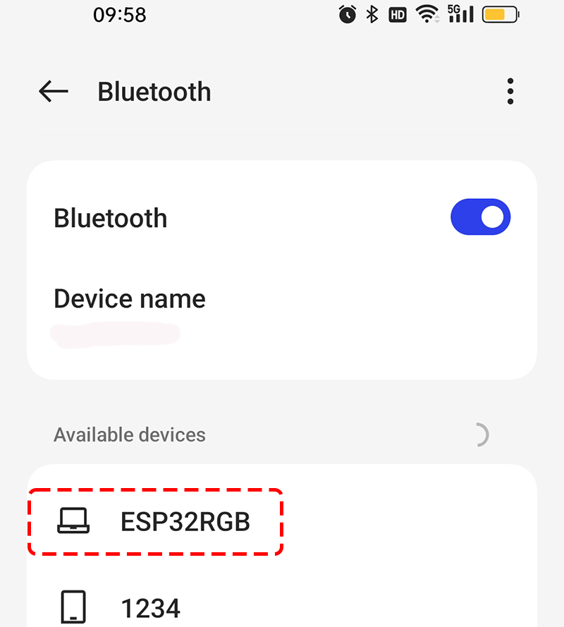
Navigate to the Bluetooth settings on your smartphone and find ESP32RGB.
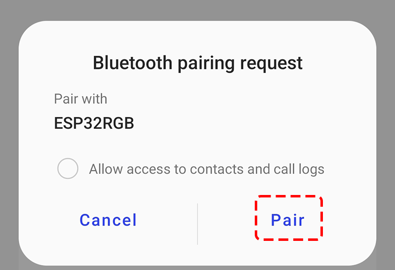
After clicking it, agree to the Pair request in the pop-up window.
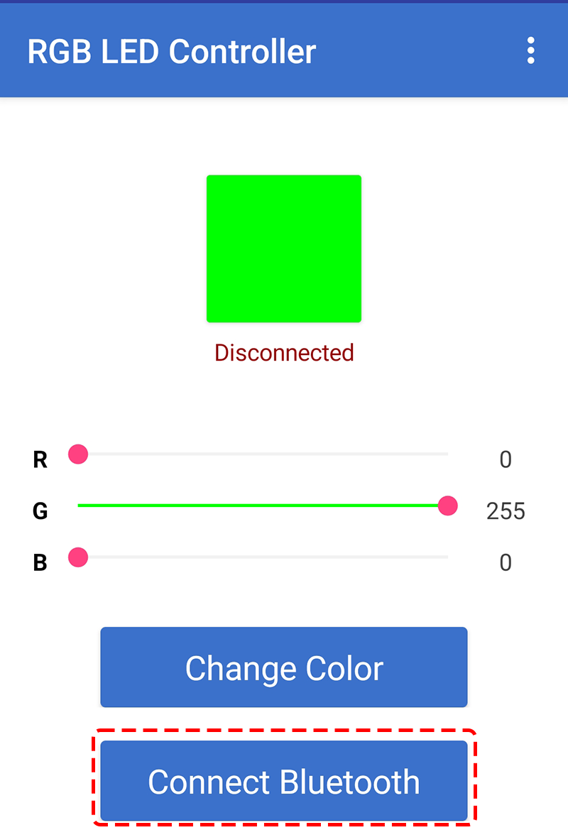
Now open the recently installed Control_RGB_LED APP.
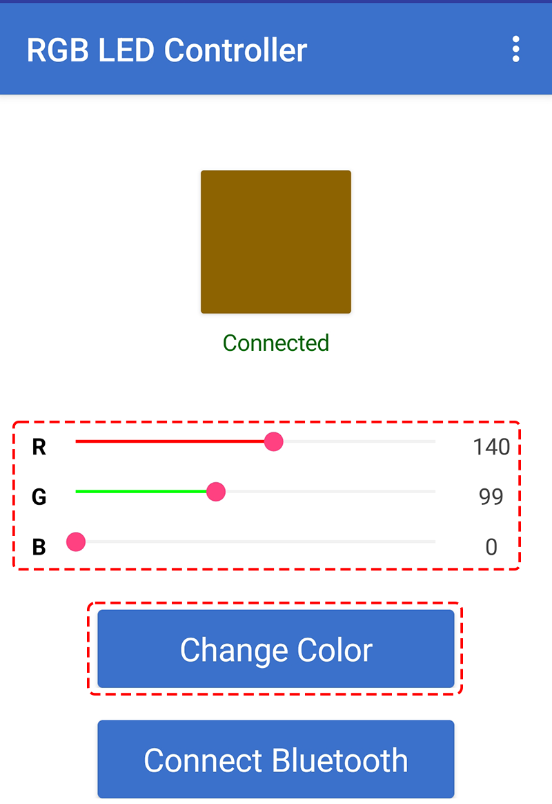
In the APP, click on Connect Bluetooth to establish a connection between the APP and ESP32.
Select the
xx.xx.xx.xx.xx.xx ESP32RGBthat comes up. if you changedSerialBT.begin("ESP32RGB");in the code, then just select the name of your setting.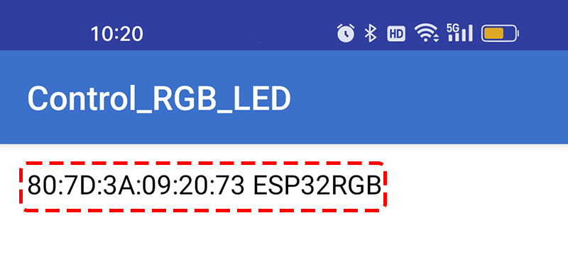
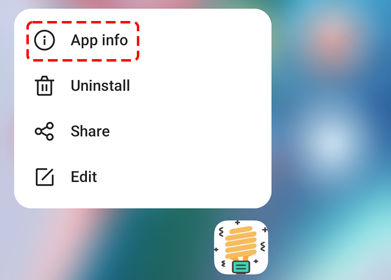
If you have been waiting for a while and still can’t see any device names, it may be that this APP is not allowed to scan surrounding devices. In this case, you need to adjust the settings manually.
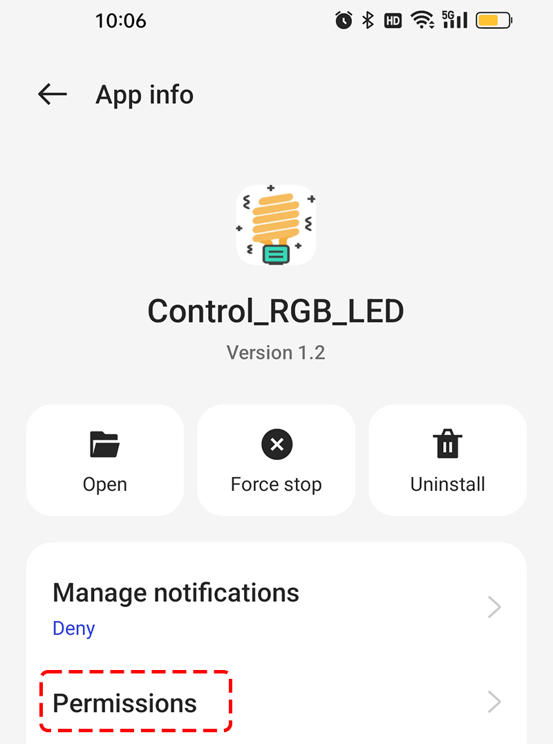
Long press the APP icon and click on the resulting APP Info. If you have another method to access this page, follow that.
Navigate to the Permissions page.
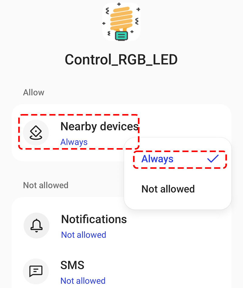
Locate Nearby devices, and select Always to allow this APP to scan for nearby devices.
Now, restart the APP and repeat steps 5 and 6 to successfully connect to Bluetooth.
Upon successful connection, you will automatically return to the main page, where it will display connected. Now you can adjust the RGB values and change the color of the RGB display by pressing the Change Color button.