Note
Hello, welcome to the SunFounder Raspberry Pi & Arduino & ESP32 Enthusiasts Community on Facebook! Dive deeper into Raspberry Pi, Arduino, and ESP32 with fellow enthusiasts.
Why Join?
Expert Support: Solve post-sale issues and technical challenges with help from our community and team.
Learn & Share: Exchange tips and tutorials to enhance your skills.
Exclusive Previews: Get early access to new product announcements and sneak peeks.
Special Discounts: Enjoy exclusive discounts on our newest products.
Festive Promotions and Giveaways: Take part in giveaways and holiday promotions.
👉 Ready to explore and create with us? Click [here] and join today!
7.2 Bluetooth Control RGB LED
This project is an extension of a previous project(7.1 Bluetooth), adding RGB LED configurations and custom commands such as “led_off”, “red”, “green”, etc. These commands allow the RGB LED to be controlled by sending commands from a mobile device using LightBlue.
Required Components
In this project, we need the following components.
It’s definitely convenient to buy a whole kit, here’s the link:
Name |
ITEMS IN THIS KIT |
LINK |
|---|---|---|
ESP32 Starter Kit |
320+ |
You can also buy them separately from the links below.
COMPONENT INTRODUCTION |
PURCHASE LINK |
|---|---|
Operation Steps
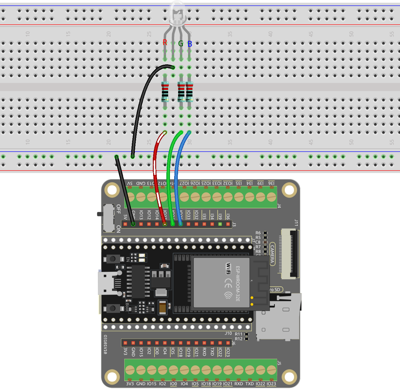
Build the circuit.
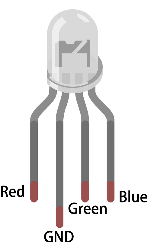
The RGB LED has 4 pins: the long pin is the common cathode pin, which is usually connected to GND; the left pin next to the longest pin is Red; and the two pins on the right are Green and Blue.
Open the
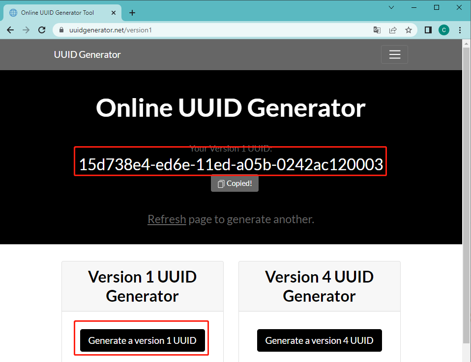
7.2_bluetooth_rgb_led.inofile located in theesp32-starter-kit-main\c\codes\7.2_bluetooth_rgb_leddirectory, or copy the code into the Arduino IDE.To avoid UUID conflicts, it is recommended to randomly generate three new UUIDs using the Online UUID Generator provided by the Bluetooth SIG, and fill them in the following lines of code.
Note
If you have already generated three new UUIDs in the 7.1 Bluetooth project, then you can continue using them.
#define SERVICE_UUID           "your_service_uuid_here"
#define CHARACTERISTIC_UUID_RX "your_rx_characteristic_uuid_here"
#define CHARACTERISTIC_UUID_TX "your_tx_characteristic_uuid_here"
Select the correct board and port, then click the Upload button.
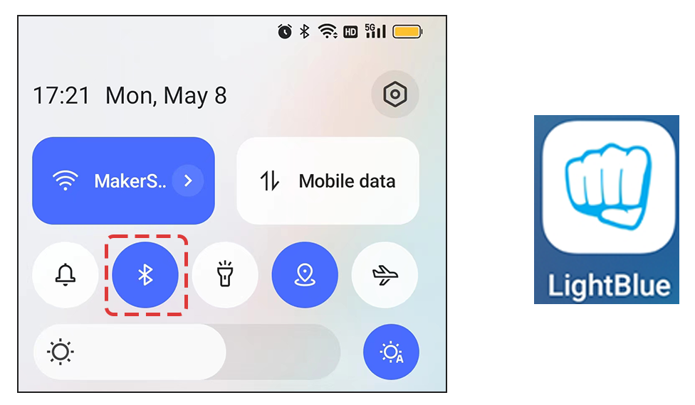
After the code has been successfully uploaded, turn on Bluetooth on your mobile device and open the LightBlue app.
On the Scan page, find ESP32-Bluetooth and click CONNECT. If you don’t see it, try refreshing the page a few times. When “Connected to device!” appears, the Bluetooth connection is successful. Scroll down to see the three UUIDs set in the code.
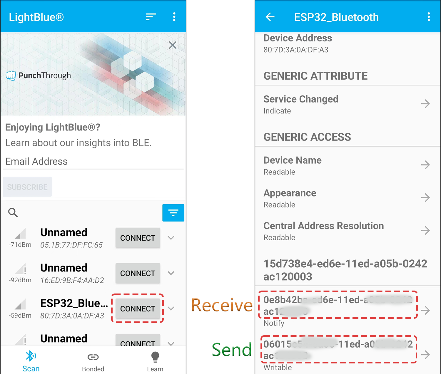
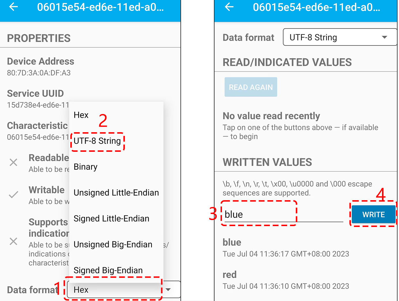
Tap the Send UUID, then set the data format to “UTF-8 String”. Now you can write these commands: “led_off”, “red”, “green”, “blue”, “yellow”, and “purple” to see if the RGB LED responds to these instructions.
How it works?
This code is an extension of a previous project(7.1 Bluetooth), adding RGB LED configurations and custom commands such as “led_off”, “red”, “green”, etc. These commands allow the RGB LED to be controlled by sending commands from a mobile device using LightBlue.
Let’s break down the code step by step:
Add new global variables for the RGB LED pins, PWM channels, frequency, and resolution.
...

// Define RGB LED pins
const int redPin = 27;
const int greenPin = 26;
const int bluePin = 25;

...
Within the
setup()function, the PWM channels are initialized with the predefined frequency and resolution. The RGB LED pins are then attached to their respective PWM channels.void setup() { ... ledcAttach(redPin, freq, resolution); ledcAttach(greenPin, freq, resolution); ledcAttach(bluePin, freq, resolution); }
Modify the
onWritemethod in theMyCharacteristicCallbacksclass. This function listens for data coming from the Bluetooth connection. Based on the received string (like"led_off","red","green", etc.), it controls the RGB LED.// Define the BLE characteristic callbacks class MyCharacteristicCallbacks : public BLECharacteristicCallbacks { void onWrite(BLECharacteristic *pCharacteristic) { std::string value = std::string(pCharacteristic->getValue().c_str()); if (value == "led_off") { setColor(0, 0, 0); // turn the RGB LED off Serial.println("RGB LED turned off"); } else if (value == "red") { setColor(255, 0, 0); // Red Serial.println("red"); } else if (value == "green") { setColor(0, 255, 0); // green Serial.println("green"); } else if (value == "blue") { setColor(0, 0, 255); // blue Serial.println("blue"); } else if (value == "yellow") { setColor(255, 150, 0); // yellow Serial.println("yellow"); } else if (value == "purple") { setColor(80, 0, 80); // purple Serial.println("purple"); } } };
Finally, a function is added to set the RGB LED color.
void setColor(int red, int green, int blue) {
    // For common-anode RGB LEDs, use 255 minus the color value
    ledcWrite(redPin, red);
    ledcWrite(greenPin, green);
    ledcWrite(bluePin, blue);
}
In summary, this script enables a remote control interaction model, where the ESP32 operates as a Bluetooth Low Energy (BLE) server.
The connected BLE client (like a smartphone) can send string commands to change the color of an RGB LED. The ESP32 also gives feedback to the client by sending back the string received, allowing the client to know what operation was performed.