Note
Hello, welcome to the SunFounder Raspberry Pi & Arduino & ESP32 Enthusiasts Community on Facebook! Dive deeper into Raspberry Pi, Arduino, and ESP32 with fellow enthusiasts.
Why Join?
Expert Support: Solve post-sale issues and technical challenges with help from our community and team.
Learn & Share: Exchange tips and tutorials to enhance your skills.
Exclusive Previews: Get early access to new product announcements and sneak peeks.
Special Discounts: Enjoy exclusive discounts on our newest products.
Festive Promotions and Giveaways: Take part in giveaways and holiday promotions.
👉 Ready to explore and create with us? Click [here] and join today!
2.1 Hello, LED!
Just as printing “Hello, world!” is the first step in learning to program, using a program to drive an LED is the traditional introduction to learning physical programming.
Required Components
In this project, we need the following components.
It’s definitely convenient to buy a whole kit, here’s the link:
Name |
ITEMS IN THIS KIT |
LINK |
|---|---|---|
ESP32 Starter Kit |
320+ |
You can also buy them separately from the links below.
COMPONENT INTRODUCTION |
PURCHASE LINK |
|---|---|
Available Pins
Here is a list of available pins on the ESP32 board for this project.
Available Pins |
IO13, IO12, IO14, IO27, IO26, IO25, IO33, IO32, IO15, IO2, IO0, IO4, IO5, IO18, IO19, IO21, IO22, IO23 |
Schematic
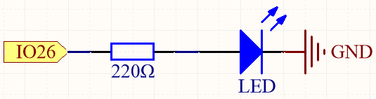
This circuit works on a simple principle, and the current direction is shown in the figure. The LED will light up after the 220ohm current limiting resistor when pin26 outputs high level. The LED will turn off when pin26 outputs low level.
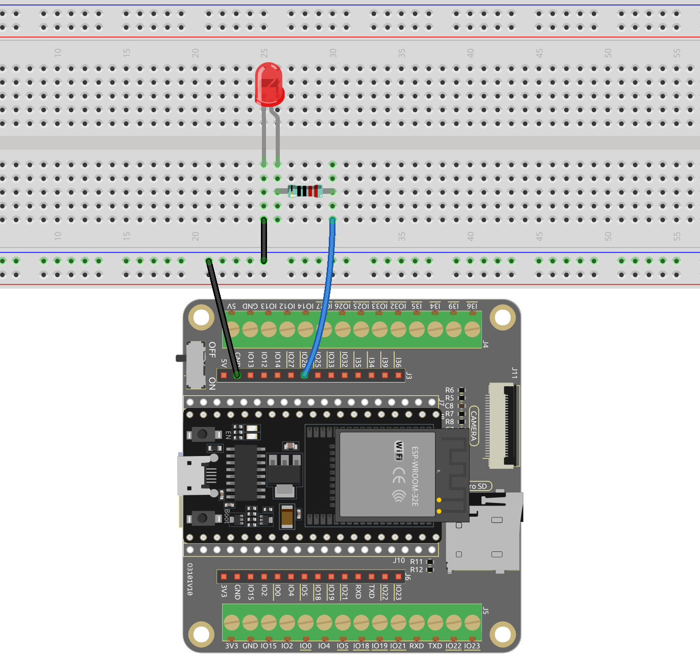
Wiring
Upload Code
You can open the file
2.1_hello_led.inounder the path ofesp32-starter-kit-main\c\codes\2.1_hello_led. Or copy this code to the Arduino IDE directly .Then connect the ESP32 board to your computer using a USB cable.
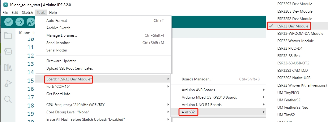
Select the board (ESP32 Dev Module) and the appropriate port.
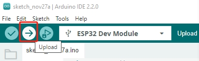
Now, click the Upload button to upload the code to the ESP32 board.
After the code is uploaded successfully, you will see the LED blinking.
How it works?
Declare an integer constant named
ledPinand assigns it the value 26.const int ledPin = 26; // The GPIO pin for the LED
Now, initialize the pin in the
setup()function, where you need to initialize the pin toOUTPUTmode.void setup() { pinMode(ledPin, OUTPUT); }
void pinMode(uint8_t pin, uint8_t mode);: This function is used to define the GPIO operation mode for a specific pin.pindefines the GPIO pin number.modesets operation mode.
The following modes are supported for the basic input and output:
INPUTsets the GPIO as input without pullup or pulldown (high impedance).OUTPUTsets the GPIO as output/read mode.INPUT_PULLDOWNsets the GPIO as input with the internal pulldown.INPUT_PULLUPsets the GPIO as input with the internal pullup.
The
loop()function contains the main logic of the program and runs continuously. It alternates between setting the pin high and low, with one-second intervals between the changes.void loop() { digitalWrite(ledPin, HIGH); // turn the LED on (HIGH is the voltage level) delay(1000); // wait for a second digitalWrite(ledPin, LOW); // turn the LED off by making the voltage LOW delay(1000); // wait for a second }
void digitalWrite(uint8_t pin, uint8_t val);: This function sets the state of the selected GPIO toHIGHorLOW. This function is only used if thepinModewas configured asOUTPUT.pindefines the GPIO pin number.valset the output digital state toHIGHorLOW.