Note
Hello, welcome to the SunFounder Raspberry Pi & Arduino & ESP32 Enthusiasts Community on Facebook! Dive deeper into Raspberry Pi, Arduino, and ESP32 with fellow enthusiasts.
Why Join?
Expert Support: Solve post-sale issues and technical challenges with help from our community and team.
Learn & Share: Exchange tips and tutorials to enhance your skills.
Exclusive Previews: Get early access to new product announcements and sneak peeks.
Special Discounts: Enjoy exclusive discounts on our newest products.
Festive Promotions and Giveaways: Take part in giveaways and holiday promotions.
👉 Ready to explore and create with us? Click [here] and join today!
4.1 Motor
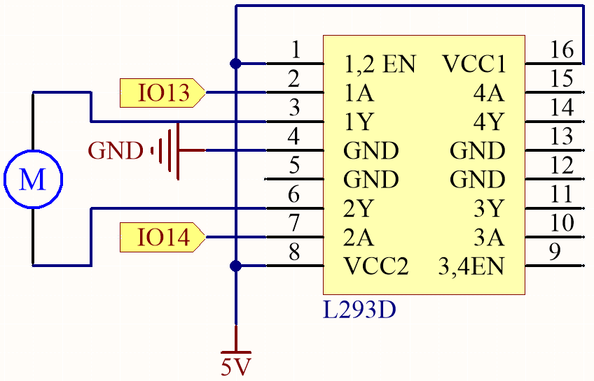
In this engaging project, we’ll explore how to drive a motor using the L293D.
The L293D is a versatile integrated circuit (IC) commonly used for motor control in electronics and robotics projects. It can drive two motors in both forward and reverse directions, making it a popular choice for applications requiring precise motor control.
By the end of this captivating project, you will have gained a thorough understanding of how digital signals and PWM signals can effectively be utilized to control motors. This invaluable knowledge will prove to be a solid foundation for your future endeavors in robotics and mechatronics. Buckle up and get ready to dive into the exciting world of motor control with the L293D!
Required Components
In this project, we need the following components.
It’s definitely convenient to buy a whole kit, here’s the link:
Name |
ITEMS IN THIS KIT |
LINK |
|---|---|---|
ESP32 Starter Kit |
320+ |
You can also buy them separately from the links below.
COMPONENT INTRODUCTION |
PURCHASE LINK |
|---|---|
- |
Available Pins
Here is a list of available pins on the ESP32 board for this project.
Available Pins |
IO13, IO14, IO27, IO26, IO25, IO33, IO32, IO15, IO2, IO0, IO4, IO5, IO18, IO19, IO21, IO22, IO23 |
Schematic
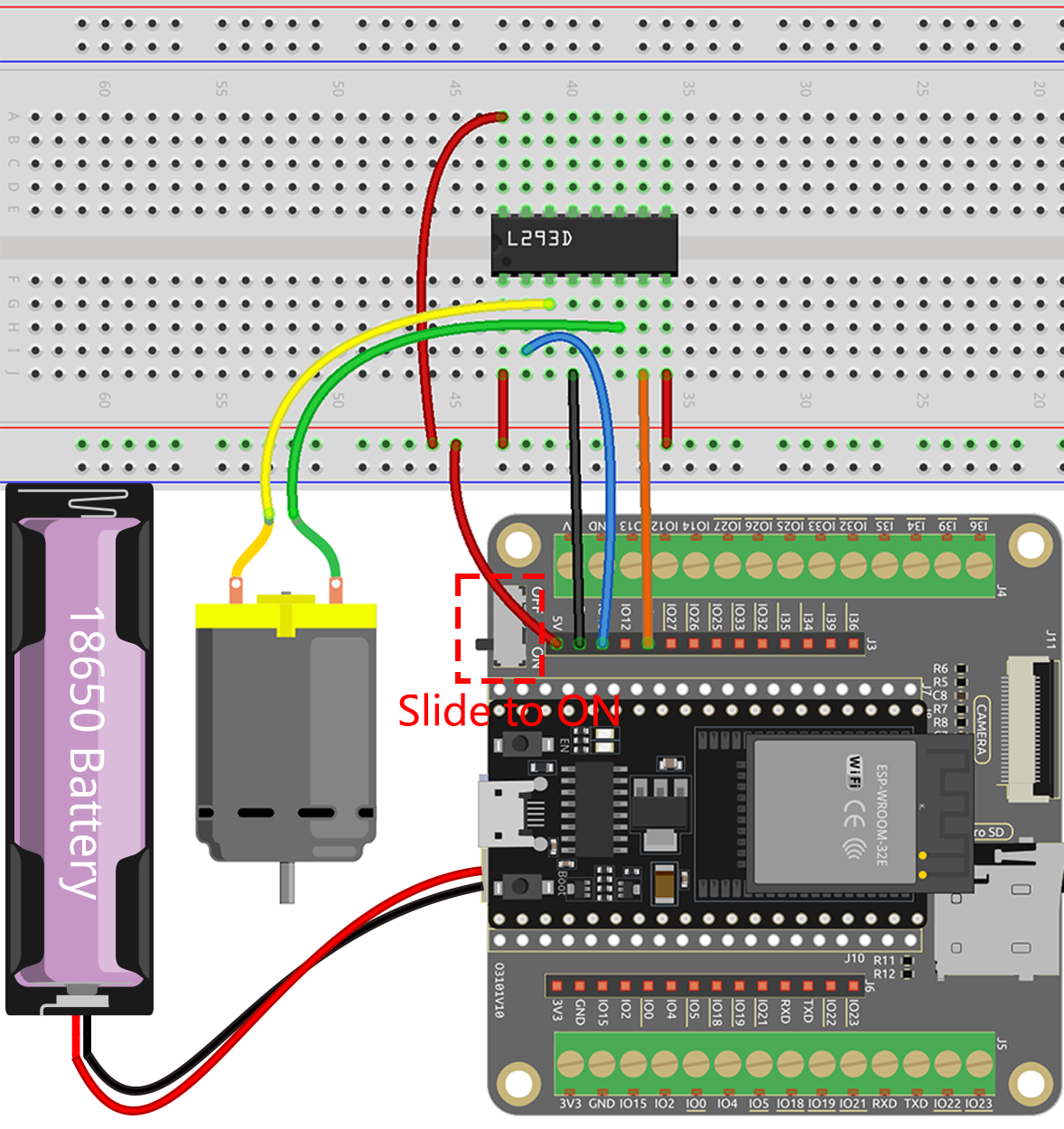
Wiring
Note
Since the motor requires a relatively high current, it is necessary to first insert the Power Pack and then slide the switch on the expansion board to the ON position to activate the power supply.
Code
Note
Open the
4.1_motor.inofile under the path ofesp32-starter-kit-main\c\codes\4.1_motor.After selecting the board (ESP32 Dev Module) and the appropriate port, click the Upload button.
Once the code is successfully uploaded, you will observe the motor rotating clockwise for one second, then counter-clockwise for one second, followed by a two-second pause. This sequence of actions will continue in an endless loop.
Learn More
In addition to simply making the motor rotate clockwise and counterclockwise, you can also control the speed of the motor’s rotation by using pulse-width modulation (PWM) on the control pin, as shown below.
Note
Open the
4.1_motor_pwm.inofile under the path ofesp32-starter-kit-main\c\codes\4.1_motor_pwm.After selecting the board (ESP32 Dev Module) and the appropriate port, click the Upload button.
The previous code directly sets the two pins of the motor to high or low voltage levels to control the motor’s rotation and stopping.
Here we use the LEDC (LED control) peripheral to generate PWM signals to control the motor’s speed. Through two for loops, the duty cycle of channel A is increased or decreased from 0 to 255 while keeping channel B at 0.
This way, you can observe the motor gradually increasing its speed to 255, then decreasing to 0, infinitely looping like this.
If you want the motor to rotate in the opposite direction, simply swap the values of channel A and channel B.