Note
Hello, welcome to the SunFounder Raspberry Pi & Arduino & ESP32 Enthusiasts Community on Facebook! Dive deeper into Raspberry Pi, Arduino, and ESP32 with fellow enthusiasts.
Why Join?
Expert Support: Solve post-sale issues and technical challenges with help from our community and team.
Learn & Share: Exchange tips and tutorials to enhance your skills.
Exclusive Previews: Get early access to new product announcements and sneak peeks.
Special Discounts: Enjoy exclusive discounts on our newest products.
Festive Promotions and Giveaways: Take part in giveaways and holiday promotions.
👉 Ready to explore and create with us? Click [here] and join today!
5.4 Detect the Line
The line-tracking module is used to detect the presence of black areas on the ground, such as black lines taped with electrical tape.
Its emitter emits appropriate infrared light into the ground, which is relatively absorbed and weakly reflected by black surfaces. The opposite is true for white surfaces. If reflected light is detected, the ground is currently indicated as white. If it is not detected, it is indicated as black.
Required Components
In this project, we need the following components.
It’s definitely convenient to buy a whole kit, here’s the link:
Name |
ITEMS IN THIS KIT |
LINK |
|---|---|---|
ESP32 Starter Kit |
320+ |
You can also buy them separately from the links below.
COMPONENT INTRODUCTION |
PURCHASE LINK |
|---|---|
Available Pins
Available Pins
Here is a list of available pins on the ESP32 board for this project.
Available Pins
IO13, IO14, IO27, IO26, IO25, IO33, I35, I34, I39, I36, IO4, IO18, IO19, IO21, IO22, IO23
Strapping Pins (Input)
Strapping pins are a special set of pins that are used to determine specific boot modes during device startup (i.e., power-on reset).
Strapping Pins
IO5, IO0, IO2, IO12, IO15
Generally, it is not recommended to use them as input pins. If you wish to use these pins, consider the potential impact on the booting process. For more details, please refer to the Strapping Pins section.
Schematic
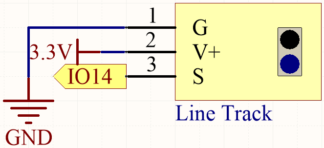
When the line tracking module detects a black line, IO14 returns a high level. On the other hand, when it detects a white line, IO14 returns a low level. You can adjust the blue potentiometer to modify the sensitivity of this module’s detection.
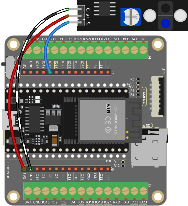
Wiring
Code
Note
You can open the file
5.4_detect_the_line.inounder the path ofesp32-starter-kit-main\c\codes\5.4_detect_the_line.After selecting the board (ESP32 Dev Module) and the appropriate port, click the Upload button.
Set the serial communication baud rate to 115200.
If the line tracking module detects a black line after the code has been uploaded successfully, “Black” will be shown in the Serial Monitor. Otherwise, “White” will be printed.