Note
Hello, welcome to the SunFounder Raspberry Pi & Arduino & ESP32 Enthusiasts Community on Facebook! Dive deeper into Raspberry Pi, Arduino, and ESP32 with fellow enthusiasts.
Why Join?
Expert Support: Solve post-sale issues and technical challenges with help from our community and team.
Learn & Share: Exchange tips and tutorials to enhance your skills.
Exclusive Previews: Get early access to new product announcements and sneak peeks.
Special Discounts: Enjoy exclusive discounts on our newest products.
Festive Promotions and Giveaways: Take part in giveaways and holiday promotions.
👉 Ready to explore and create with us? Click [here] and join today!
2.5 7 Segment Display
Welcome to this fascinating project! In this project, we will explore the enchanting world of displaying numbers from 0 to 9 on a seven-segment display.
Imagine triggering this project and witnessing a small, compact display glowing brightly with each number from 0 to 9. It’s like having a miniature screen that showcases the digits in a captivating way. By controlling the signal pins, you can effortlessly change the displayed number and create various engaging effects.
Through simple circuit connections and programming, you will learn how to interact with the seven-segment display and bring your desired numbers to life. Whether it’s a counter, a clock, or any other intriguing application, the seven-segment display will be your reliable companion, adding a touch of brilliance to your projects.
Required Components
In this project, we need the following components.
It’s definitely convenient to buy a whole kit, here’s the link:
Name |
ITEMS IN THIS KIT |
LINK |
|---|---|---|
ESP32 Starter Kit |
320+ |
You can also buy them separately from the links below.
COMPONENT INTRODUCTION |
PURCHASE LINK |
|---|---|
Available Pins
Here is a list of available pins on the ESP32 board for this project.
Available Pins |
IO13, IO12, IO14, IO27, IO26, IO25, IO33, IO32, IO15, IO2, IO0, IO4, IO5, IO18, IO19, IO21, IO22, IO23 |
Schematic
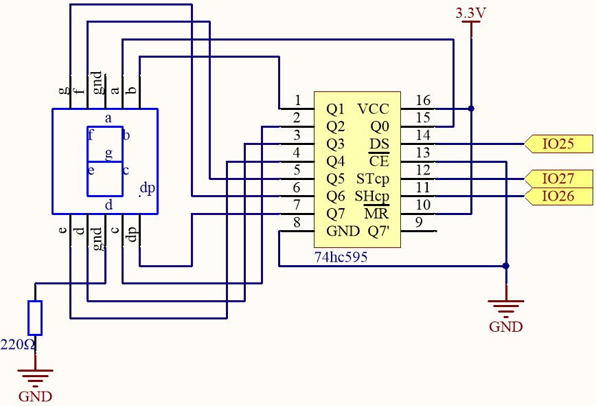
Here the wiring principle is basically the same as 2.4 Microchip - 74HC595, the only difference is that Q0-Q7 are connected to the a ~ g pins of the 7 Segment Display.
74HC595 |
LED Segment Display |
|---|---|
Q0 |
a |
Q1 |
b |
Q2 |
c |
Q3 |
d |
Q4 |
e |
Q5 |
f |
Q6 |
g |
Q7 |
dp |
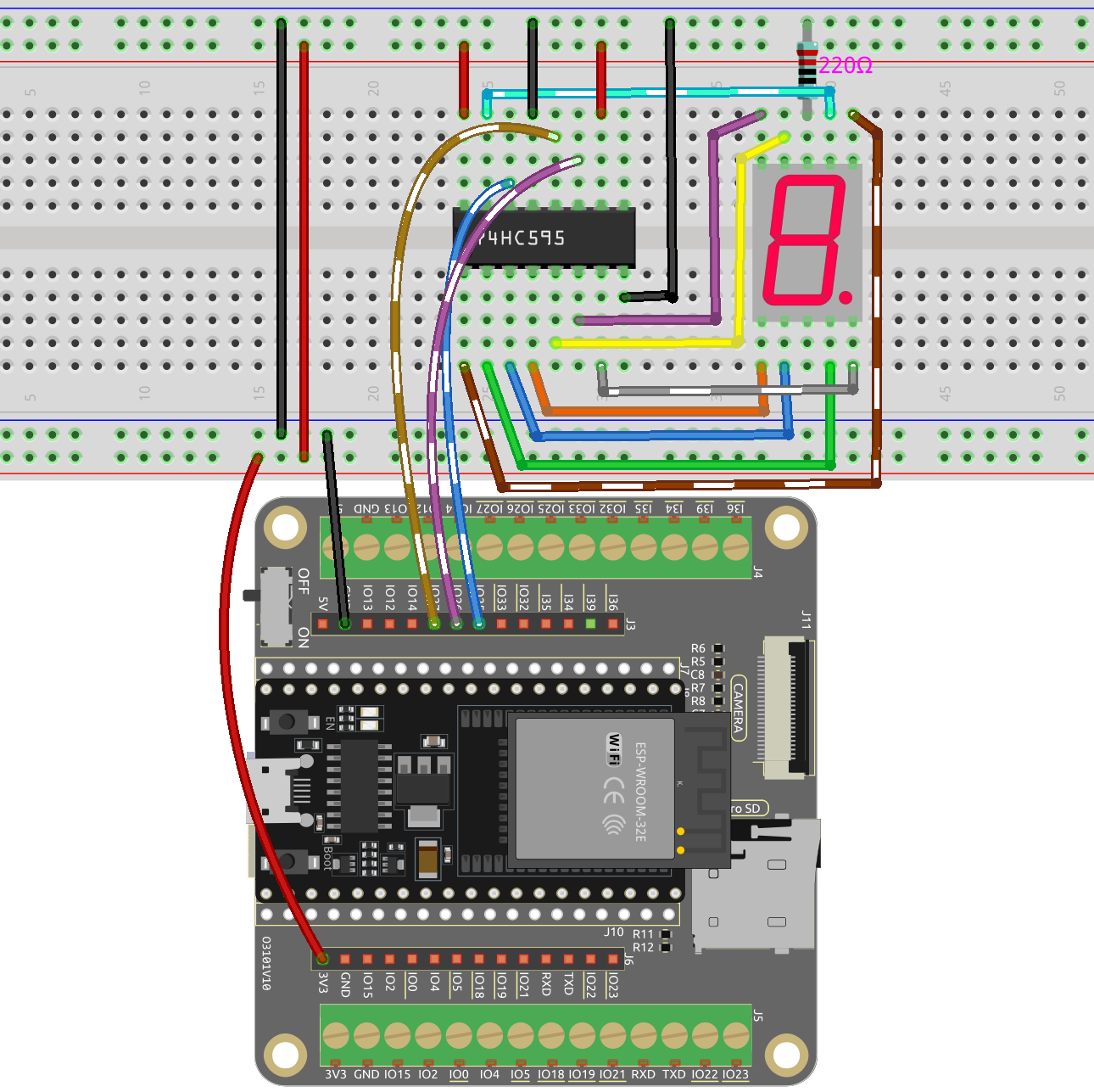
Wiring
Code
Note
Open the
2.5_7segment.inofile under the path ofesp32-starter-kit-main\c\codes\2.5_7segment.After selecting the board (ESP32 Dev Module) and the appropriate port, click the Upload button.
After the code is uploaded successfully, you will be able to see the LED Segment Display display 0~9 in sequence.
How it works?
In this project, we are using the shiftOut() function to write the binary number to the shift register.
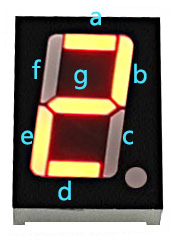
Suppose that the 7-segment Display display the number “2”. This bit pattern corresponds to the segments f, c and dp being turned off (low), while the segments a, b, d, e and g are turned on (high). This is “01011011” in binary and “0x5b” in hexadecimal notation.
Therefore, you would need to call shiftOut(DS,SHcp,MSBFIRST,0x5b) to display the number “2” on the 7-segment display.
The following table shows the hexadecimal patterns that need to be written to the shift register to display the numbers 0 to 9 on a 7-segment display.
Numbers |
Binary Code |
Hex Code |
|---|---|---|
0 |
00111111 |
0x3f |
1 |
00000110 |
0x06 |
2 |
01011011 |
0x5b |
3 |
01001111 |
0x4f |
4 |
01100110 |
0x66 |
5 |
01101101 |
0x6d |
6 |
01111101 |
0x7d |
7 |
00000111 |
0x07 |
8 |
01111111 |
0x7f |
9 |
01101111 |
0x6f |
Write these codes into shiftOut() to make the LED Segment Display display the corresponding numbers.