Note
Hello, welcome to the SunFounder Raspberry Pi & Arduino & ESP32 Enthusiasts Community on Facebook! Dive deeper into Raspberry Pi, Arduino, and ESP32 with fellow enthusiasts.
Why Join?
Expert Support: Solve post-sale issues and technical challenges with help from our community and team.
Learn & Share: Exchange tips and tutorials to enhance your skills.
Exclusive Previews: Get early access to new product announcements and sneak peeks.
Special Discounts: Enjoy exclusive discounts on our newest products.
Festive Promotions and Giveaways: Take part in giveaways and holiday promotions.
👉 Ready to explore and create with us? Click [here] and join today!
8.6 Temperature and Humidity Monitoring with Adafruit IO
In this project, we will guide you on how to use a popular IoT platform. There are many free (or low-cost) platforms available online for programming enthusiasts. Some examples are Adafruit IO, Blynk, Arduino Cloud, ThingSpeak, and so on. The usage of these platforms is quite similar. Here, we will be focusing on Adafruit IO.
We will write an Arduino program that uses the DHT11 sensor to send temperature and humidity readings to Adafruit IO’s dashboard. You can also control an LED on the circuit through a switch on the dashboard.
Required Components
In this project, we need the following components.
It’s definitely convenient to buy a whole kit, here’s the link:
Name |
ITEMS IN THIS KIT |
LINK |
|---|---|---|
ESP32 Starter Kit |
320+ |
You can also buy them separately from the links below.
COMPONENT INTRODUCTION |
PURCHASE LINK |
|---|---|
Setting up the Dashboard
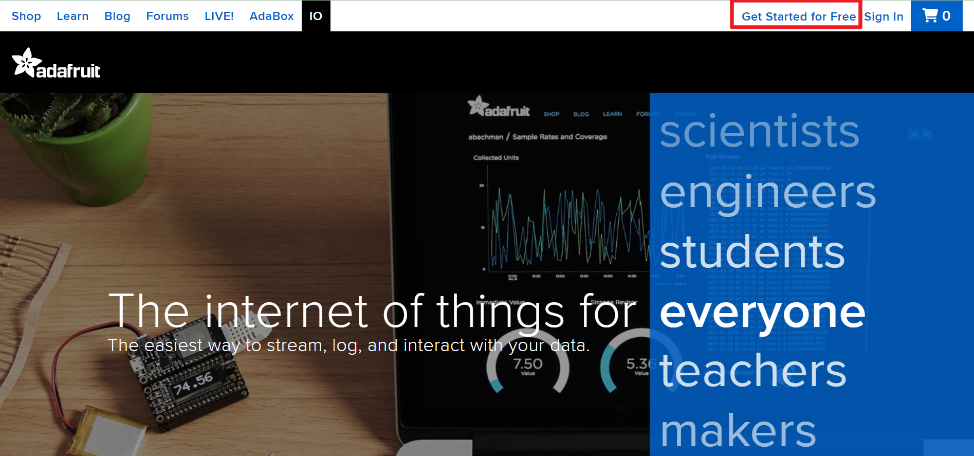
Visit Adafruit IO, then click on Start for free to create a free account.
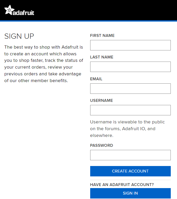
Fill out the form to create an account.
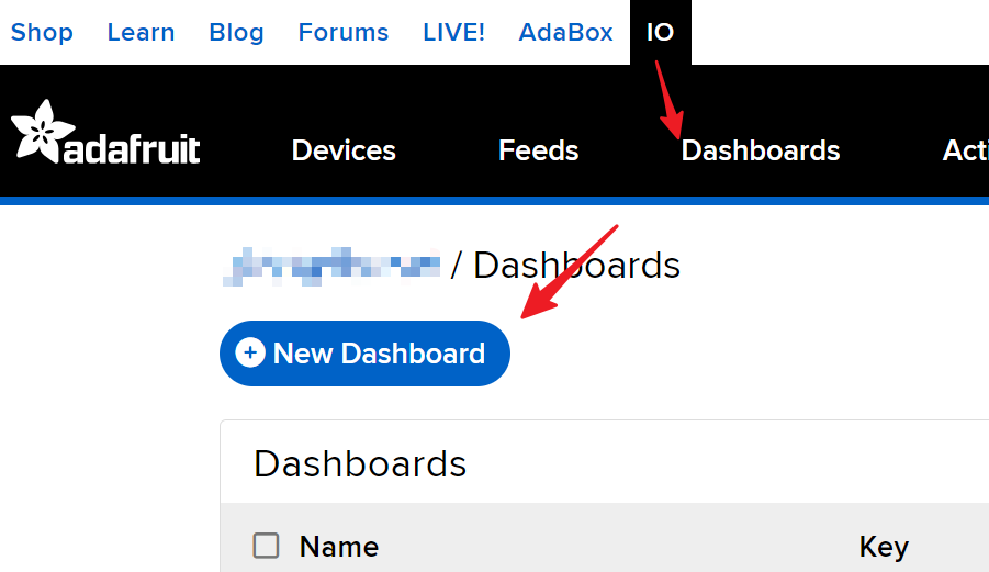
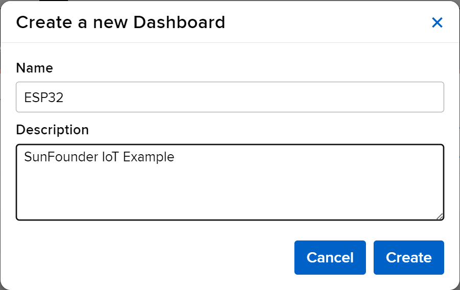
After creating an Adafruit account, you’ll need to reopen Adafruit io. Click on the Dashboards, then click on New Dashboard.
Create a New Dashboard.
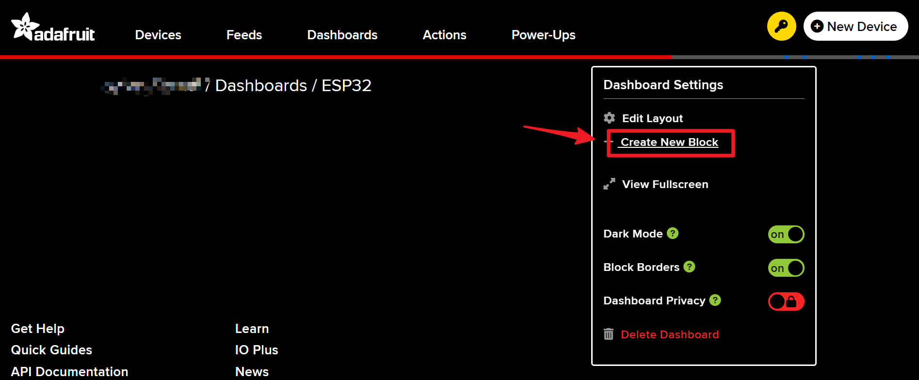
Enter the newly created Dashboard and create a new block.
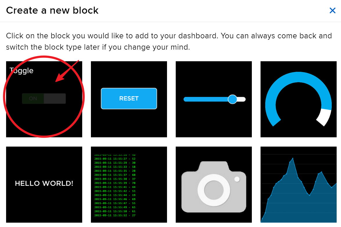
Create 1 Toggle block.
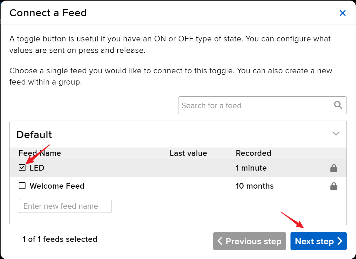
Next, you’ll need to create a new feed here. This toggle will be used to control the LED, and we’ll name this feed “LED”.
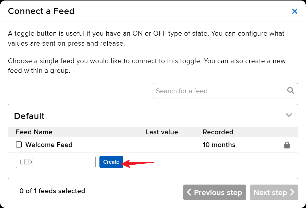
Check the LED feed, then move to the next step.
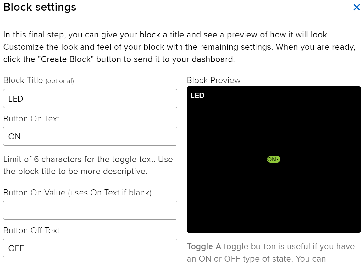
Complete the block settings (mainly Block Title, On Text, and Off Text), then click on the Create block button at the bottom right to finish.
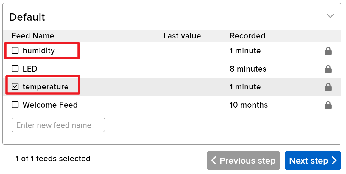
We also need to create two Text Blocks next. They will be used to display temperature and humidity. So, create two feeds named temperature and humidity.
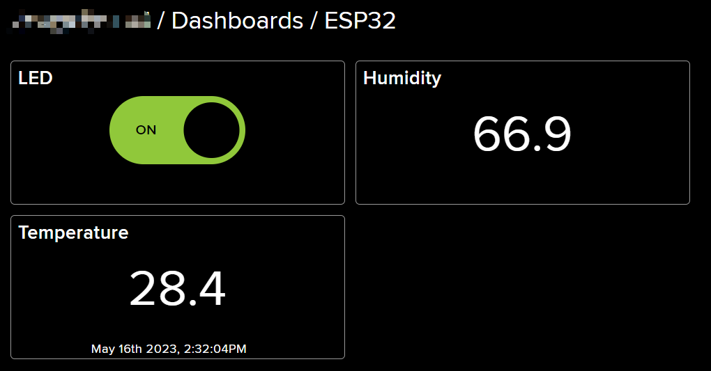
After creation, your Dashboard should look something like this:
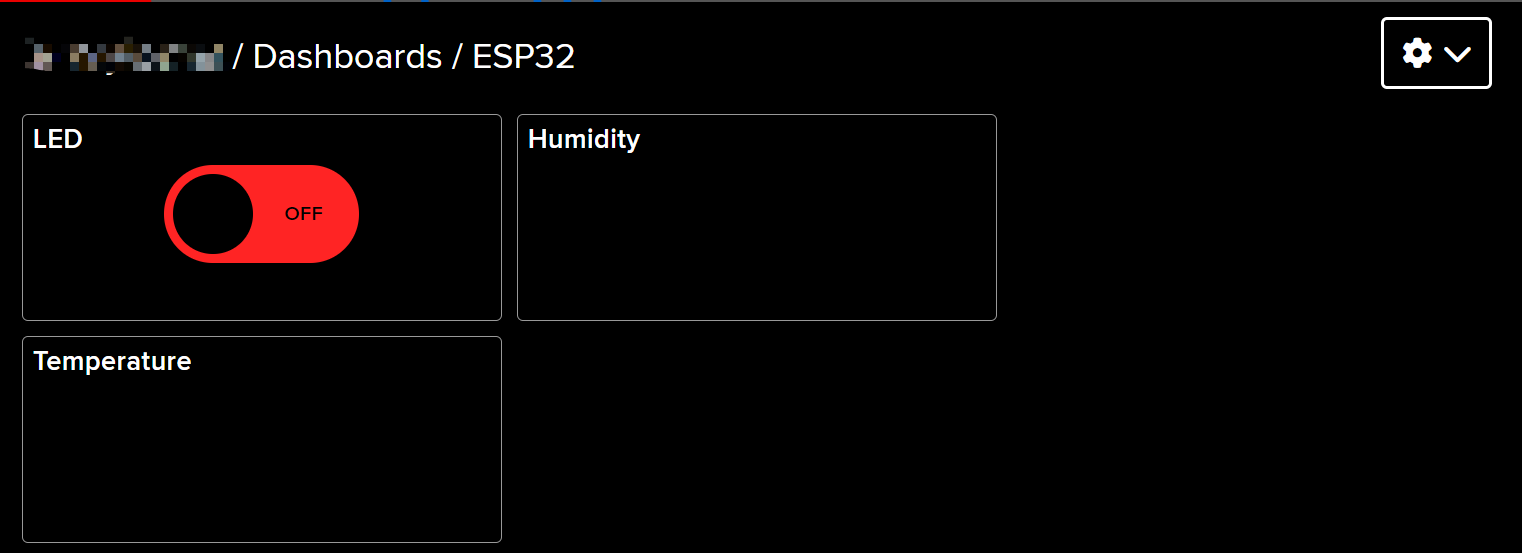
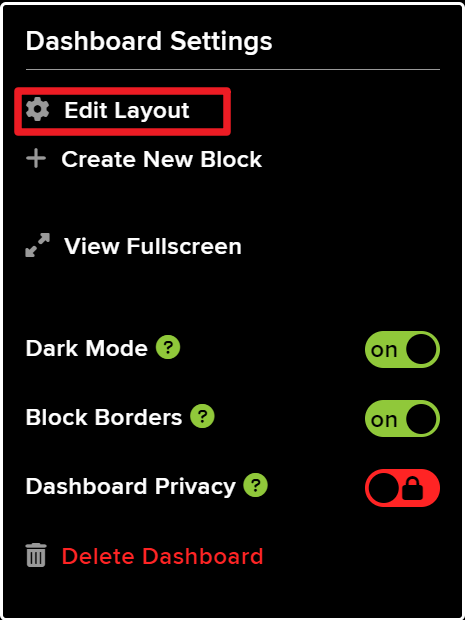
You can adjust the layout by using the Edit Layout option on the Dashboard.
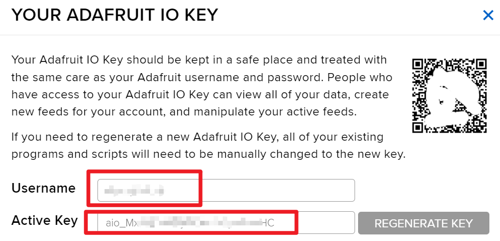
Click on API KEY, and you will see your username and API KEY displayed. Note these down as you’ll need them for your code.
Running the Code
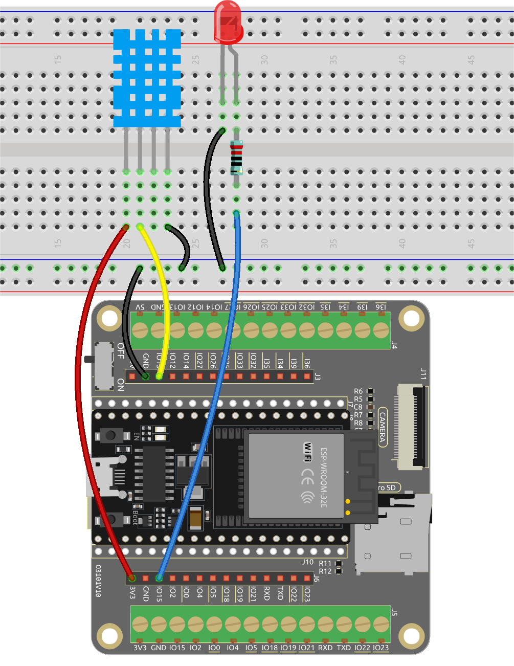
Build the circuit.
Then, connect ESP32 board to the computer using the USB cable.
Open the code.
Open the
iot_6_adafruit_io.inofile located in theesp32-starter-kit-main\c\codes\iot_6_adafruit_iodirectory, or copy the code into the Arduino IDE.After selecting the board (ESP32 Dev Module) and the appropriate port, click the Upload button.
The
Adafruit_MQTT LibraryandDHT sensor libraryare used here, you can install them from the Library Manager.
Find the following lines and replace
SSIDandPASSWORDwith the specific details of your WiFi network./************************* WiFi Access Point *********************************/ #define WLAN_SSID "SSID" #define WLAN_PASS "PASSWORD"
Then replace
YOUR_ADAFRUIT_IO_USERNAMEwith your Adafruit IO username andYOUR_ADAFRUIT_IO_KEYwith the API KEY you just copied.// Adafruit IO Account Configuration // (to obtain these values, visit https://io.adafruit.com and click on Active Key) #define AIO_USERNAME "YOUR_ADAFRUIT_IO_USERNAME" #define AIO_KEY "YOUR_ADAFRUIT_IO_KEY"
After selecting the correct board (ESP32 Dev Module) and port, click the Upload button.
Once the code is successfully uploaded, you will observe the following message in the serial monitor, indicating successful communication with Adafruit IO.
Adafruit IO MQTTS (SSL/TLS) Example


Connecting to xxxxx
WiFi connected
IP address:
192.168.18.76
Connecting to MQTT... MQTT Connected!
Temperature: 27.10
Humidity: 61.00
Navigate back to Adafruit IO. Now you can observe the temperature and humidity readings on the dashboard, or utilize the LED toggle switch to control the on/off state of the external LED connected to the circuit.