Note
Hello, welcome to the SunFounder Raspberry Pi & Arduino & ESP32 Enthusiasts Community on Facebook! Dive deeper into Raspberry Pi, Arduino, and ESP32 with fellow enthusiasts.
Why Join?
Expert Support: Solve post-sale issues and technical challenges with help from our community and team.
Learn & Share: Exchange tips and tutorials to enhance your skills.
Exclusive Previews: Get early access to new product announcements and sneak peeks.
Special Discounts: Enjoy exclusive discounts on our newest products.
Festive Promotions and Giveaways: Take part in giveaways and holiday promotions.
👉 Ready to explore and create with us? Click [here] and join today!
3.2 Custom Tone
We have used active buzzer in the previous project, this time we will use passive buzzer.
Like the active buzzer, the passive buzzer also uses the phenomenon of electromagnetic induction to work. The difference is that a passive buzzer does not have oscillating source, so it will not beep if DC signals are used. But this allows the passive buzzer to adjust its own oscillation frequency and can emit different notes such as “doh, re, mi, fa, sol, la, ti”.
Let the passive buzzer emit a melody!
Required Components
In this project, we need the following components.
It’s definitely convenient to buy a whole kit, here’s the link:
Name |
ITEMS IN THIS KIT |
LINK |
|---|---|---|
ESP32 Starter Kit |
320+ |
You can also buy them separately from the links below.
COMPONENT INTRODUCTION |
PURCHASE LINK |
|---|---|
- |
|
Available Pins
Here is a list of available pins on the ESP32 board for this project.
Available Pins |
IO13, IO12, IO14, IO27, IO26, IO25, IO33, IO32, IO15, IO2, IO0, IO4, IO5, IO18, IO19, IO21, IO22, IO23 |
Schematic

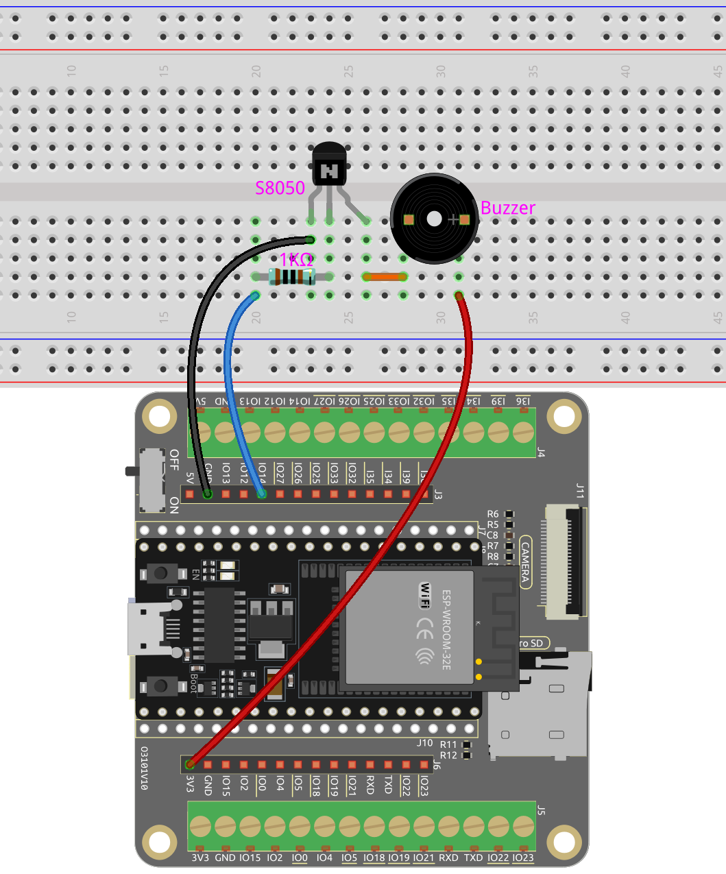
When the IO14 output is high, after the 1K current limiting resistor (to protect the transistor), the S8050 (NPN transistor) will conduct, so that the buzzer will sound.
The role of S8050 (NPN transistor) is to amplify the current and make the buzzer sound louder. In fact, you can also connect the buzzer directly to IO14, but you will find that the buzzer sound is smaller.
Wiring
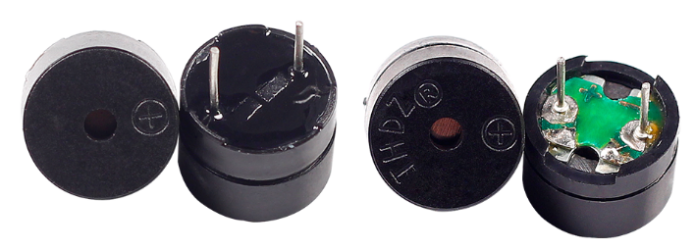
Two types of buzzers are included in the kit. We need to use passive buzzer. Turn them around, the exposed PCB is the one we want.
The buzzer needs to use a transistor when working, here we use S8050 (NPN Transistor).
Code
Note
Open the
3.2_custom_tone.inofile under the path ofesp32-starter-kit-main\c\codes\3.2_custom_tone.After selecting the board (ESP32 Dev Module) and the appropriate port, click the Upload button.
After the code is successfully uploaded, you will hear the passive buzzer play a sequence of 7 musical notes.
How it works?
Define constants for the buzzer pin and PWM resolution.
const int buzzerPin = 14; //buzzer pin
const int resolution = 8;
Define an array containing the frequencies of the 7 musical notes in Hz.
int frequencies[] = {262, 294, 330, 349, 392, 440, 494};
Create a function to play a given frequency on the buzzer for a specified duration.
void playFrequency(int frequency, int duration) {
    ledcWriteTone(buzzerPin, frequency); // Start the tone
    delay(duration); // Wait for the specified duration
    ledcWriteTone(buzzerPin, 0); // Stop the buzzer
}
uint32_t ledcWriteTone(uint8_t pin, uint32_t freq);: This function is used to setup the pin to 50 % PWM tone on selected frequency.pinselect LEDC pin.freqselect frequency of pwm signal.
This function will return
frequencyset for channel. If0is returned, error occurs and ledc cahnnel was not configured.Configure the PWM channel and attach the buzzer pin in the
setup()function.void setup() { ledcAttach(buzzerPin, 2000, resolution); // Set up the PWM pin }
bool ledcAttach(uint8_t pin, uint32_t freq, uint8_t resolution);: This function is used to setup LEDC pin with given frequency and resolution. LEDC channel will be selected automatically.pinselect GPIO pin.freqselect frequency of pwm.resolution_bitsselect resolution for ledc channel. Range is 1-14 bits (1-20 bits for ESP32).
In the
loop()function, play the sequence of 7 notes with a brief pause between each note and a 1-second pause before repeating the sequence.void loop() { for (int i = 0; i < 7; i++) { playFrequency(frequencies[i], 300); // Play each note for 300ms delay(50); // Add a brief pause between the notes } delay(1000); // Wait for 1 second before replaying the sequence }