Note
Hello, welcome to the SunFounder Raspberry Pi & Arduino & ESP32 Enthusiasts Community on Facebook! Dive deeper into Raspberry Pi, Arduino, and ESP32 with fellow enthusiasts.
Why Join?
Expert Support: Solve post-sale issues and technical challenges with help from our community and team.
Learn & Share: Exchange tips and tutorials to enhance your skills.
Exclusive Previews: Get early access to new product announcements and sneak peeks.
Special Discounts: Enjoy exclusive discounts on our newest products.
Festive Promotions and Giveaways: Take part in giveaways and holiday promotions.
👉 Ready to explore and create with us? Click [here] and join today!
5.6 Two Kinds of Transistors
This kit is equipped with two types of transistors, S8550 and S8050, the former is PNP and the latter is NPN. They look very similar, and we need to check carefully to see their labels. When a High level signal goes through an NPN transistor, it is energized. But a PNP one needs a Low level signal to manage it. Both types of transistor are frequently used for contactless switches, just like in this experiment.
Let’s use LED and button to understand how to use transistor!
Required Components
In this project, we need the following components.
It’s definitely convenient to buy a whole kit, here’s the link:
Name |
ITEMS IN THIS KIT |
LINK |
|---|---|---|
ESP32 Starter Kit |
320+ |
You can also buy them separately from the links below.
COMPONENT INTRODUCTION |
PURCHASE LINK |
|---|---|
Available Pins
Available Pins
Here is a list of available pins on the ESP32 board for this project.
For Input
IO14, IO25, I35, I34, I39, I36, IO18, IO19, IO21, IO22, IO23
For Output
IO13, IO12, IO14, IO27, IO26, IO25, IO33, IO32, IO15, IO2, IO0, IO4, IO5, IO18, IO19, IO21, IO22, IO23
Conditional Usage Pins (Input)
The following pins have built-in pull-up or pull-down resistors, so external resistors are not required when using them as input pins:
Conditional Usage Pins
Description
IO13, IO15, IO2, IO4
Pulling up with a 47K resistor defaults the value to high.
IO27, IO26, IO33
Pulling up with a 4.7K resistor defaults the value to high.
IO32
Pulling down with a 1K resistor defaults the value to low.
Strapping Pins (Input)
Strapping pins are a special set of pins that are used to determine specific boot modes during device startup (i.e., power-on reset).
Strapping Pins
IO5, IO0, IO2, IO12, IO15
Generally, it is not recommended to use them as input pins. If you wish to use these pins, consider the potential impact on the booting process. For more details, please refer to the Strapping Pins section.
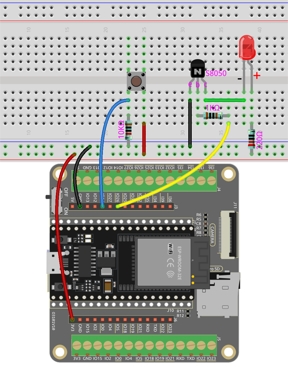
Way to connect NPN (S8050) transistor
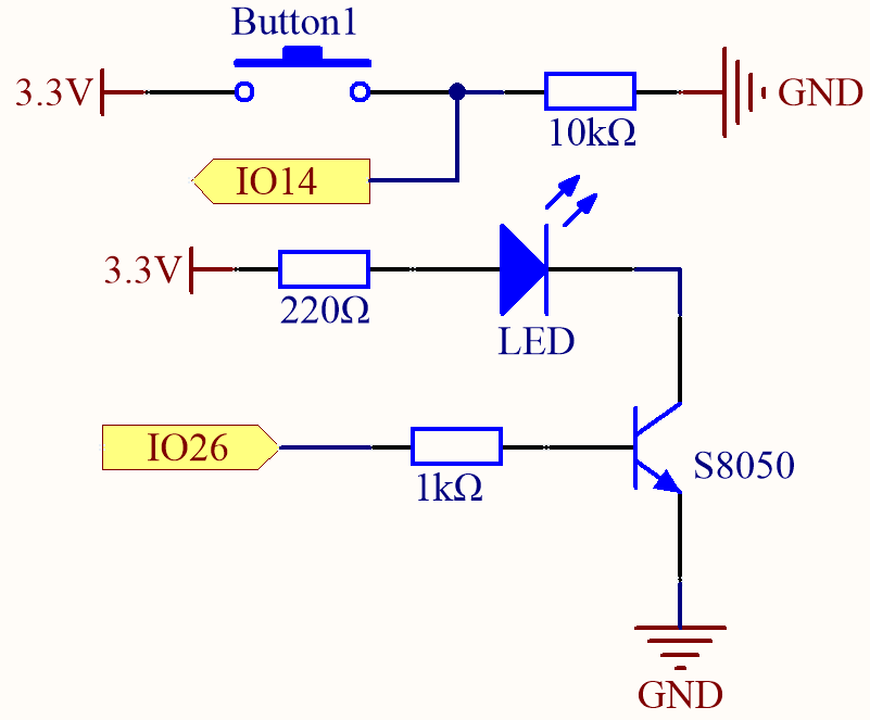
In this circuit, when the button is pressed, IO14 is high.
By programming IO26 to output high, after a 1k current limiting resistor (to protect the transistor), the S8050 (NPN transistor) is allowed to conduct, thus allowing the LED to light up.
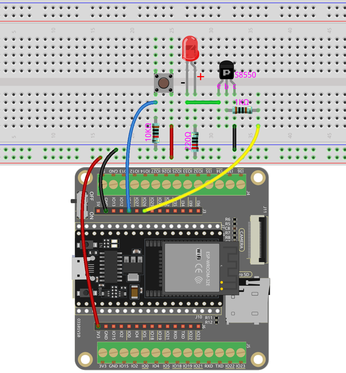
Way to connect PNP(S8550) transistor
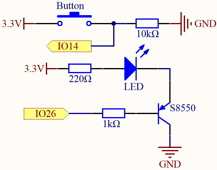
In this circuit, IO14 is low by the default and will change to high when the button is pressed.
By programming IO26 to output low, after a 1k current limiting resistor (to protect the transistor), the S8550 (PNP transistor) is allowed to conduct, thus allowing the LED to light up.
The only difference you will notice between this circuit and the previous one is that in the previous circuit the cathode of the LED is connected to the collector of the S8050 (NPN transistor), while this one is connected to the emitter of the S8550 (PNP transistor).
Code
Note
You can open the file
5.6_transistor.inounder the path ofesp32-starter-kit-main\c\codes\5.6_transistor.After selecting the board (ESP32 Dev Module) and the appropriate port, click the Upload button.
Two types of transistors can be controlled using the same code. When we press the button, the ESP32 will send a high-level signal to the transistor; when we release it, it will send a low-level signal.
The circuit using the S8050 (NPN transistor) will light up when the button is pressed, indicating that it is in a high-level conduction state;
The circuit using the S8550 (PNP transistor) will light up when the button is released, indicating that it is in a low-level conduction state.