Note
Hello, welcome to the SunFounder Raspberry Pi & Arduino & ESP32 Enthusiasts Community on Facebook! Dive deeper into Raspberry Pi, Arduino, and ESP32 with fellow enthusiasts.
Why Join?
Expert Support: Solve post-sale issues and technical challenges with help from our community and team.
Learn & Share: Exchange tips and tutorials to enhance your skills.
Exclusive Previews: Get early access to new product announcements and sneak peeks.
Special Discounts: Enjoy exclusive discounts on our newest products.
Festive Promotions and Giveaways: Take part in giveaways and holiday promotions.
👉 Ready to explore and create with us? Click [here] and join today!
2.7 RGB LED Strip
In this project, we will delve into the mesmerizing world of driving WS2812 LED strips and bring a vibrant display of colors to life. With the ability to individually control each LED on the strip, we can create captivating lighting effects that will dazzle the senses.
Furthermore, we have included an exciting extension to this project, where we will explore the realm of randomness. By introducing random colors and implementing a flowing light effect, we can create a mesmerizing visual experience that captivates and enchants.
Required Components
In this project, we need the following components.
It’s definitely convenient to buy a whole kit, here’s the link:
Name |
ITEMS IN THIS KIT |
LINK |
|---|---|---|
ESP32 Starter Kit |
320+ |
You can also buy them separately from the links below.
COMPONENT INTRODUCTION |
PURCHASE LINK |
|---|---|
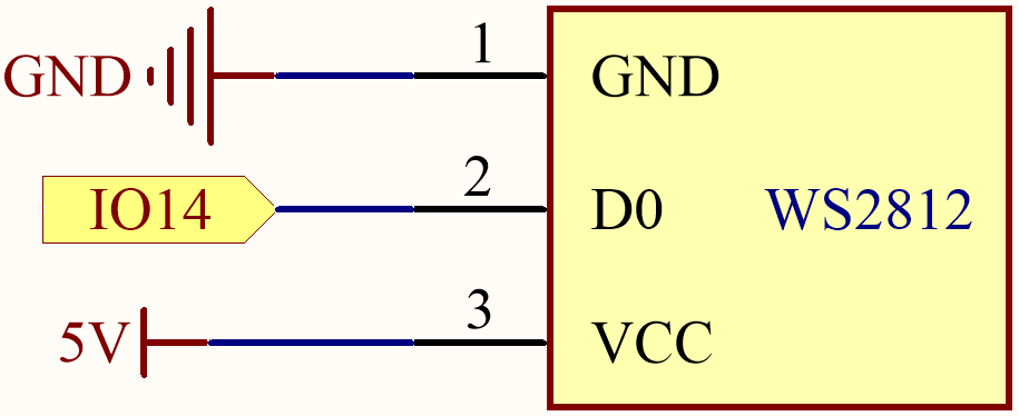
Schematic
Available Pins
Here is a list of available pins on the ESP32 board for this project.
Available Pins |
IO13, IO12, IO14, IO27, IO26, IO25, IO32, IO15, IO2, IO0, IO4, IO5, IO18, IO19, IO21, IO22, IO23 |
Note
IO33 is not available for this project.
The WS2812 LED strip is a type of LED strip that requires a precise pulse-width modulation (PWM) signal. The PWM signal has precise requirements in both time and voltage. For instance, a “0” bit for the WS2812 corresponds to a high-level pulse of about 0.4 microseconds, while a “1” bit corresponds to a high-level pulse of about 0.8 microseconds. This means the strip needs to receive high-frequency voltage changes.
However, with a 4.7K pull-up resistor and a 100nf pull-down capacitor on IO33, a simple low-pass filter is created. This type of circuit “smooths out” high-frequency signals, because the capacitor needs some time to charge and discharge when it receives voltage changes. Therefore, if the signal changes too quickly (i.e., is high-frequency), the capacitor will not be able to keep up. This results in the output signal becoming blurred and unrecognizable to the strip.
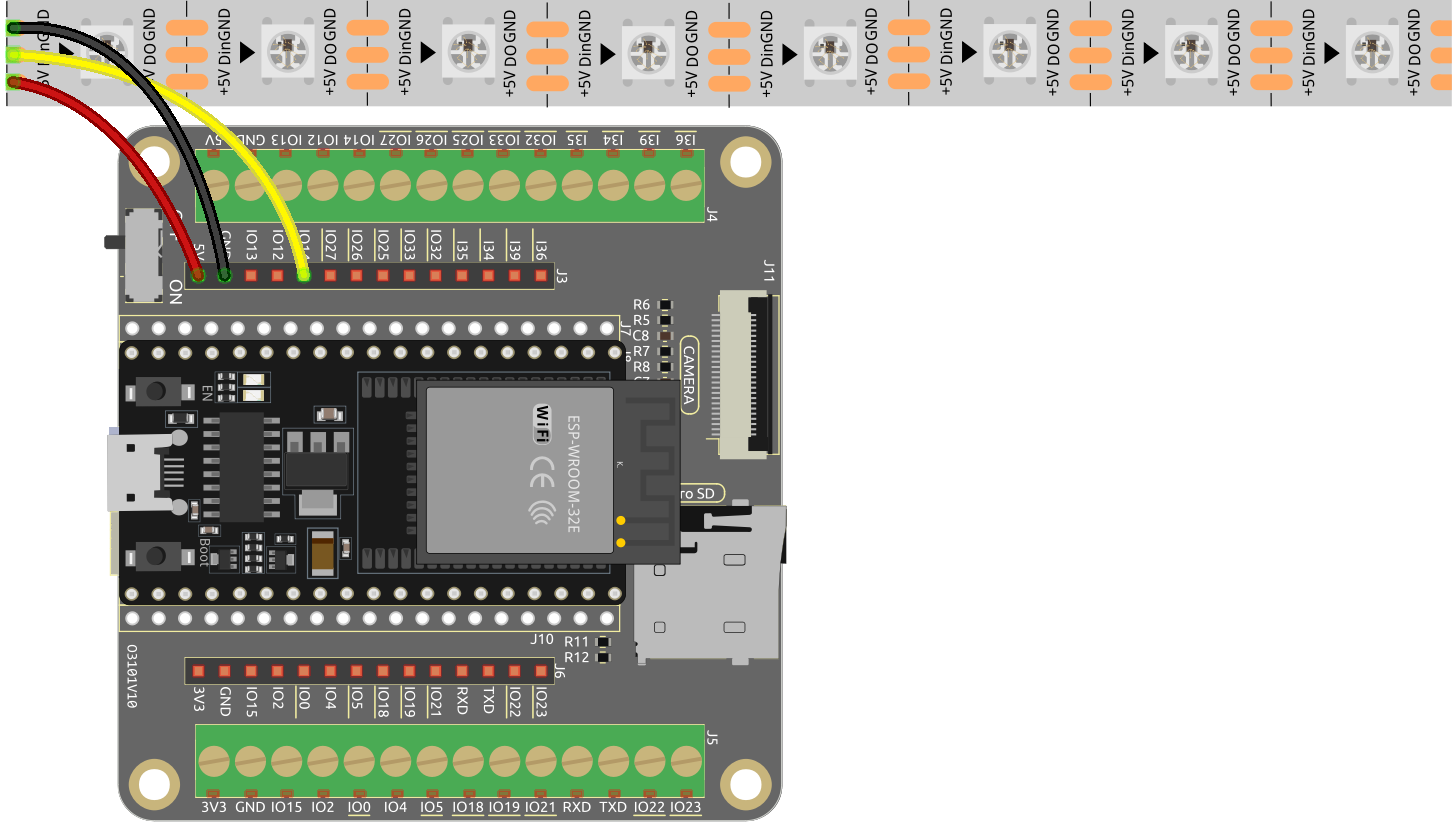
Wiring
Code
Note
You can open the file
2.7_rgb_strip.inounder the path ofesp32-starter-kit-main\c\codes\2.7_rgb_strip. Or copy this code into Arduino IDE.After selecting the board (ESP32 Dev Module) and the appropriate port, click the Upload button.
The
Adafruit NeoPixellibrary is used here, you can install it from the Library Manager.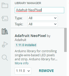
When the code is successfully uploaded, the LEDs on the strip will sequentially turn on with a yellow color and then turn off, creating a simple chasing effect.
How it works?
Include the Adafruit NeoPixel library: This line imports the Adafruit NeoPixel library so that the sketch can use its functions and classes to control the LED strip.
#include <Adafruit_NeoPixel.h> // Include the Adafruit NeoPixel library
Define constants for the LED strip.
#define LED_PIN 13 // NeoPixel LED strip
#define NUM_LEDS 8 // Number of LEDs
Create an instance of the Adafruit_NeoPixel class.
// Create an instance of the Adafruit_NeoPixel class
 Adafruit_NeoPixel strip = Adafruit_NeoPixel(NUM_LEDS, LED_PIN, NEO_GRB + NEO_KHZ800);
This line creates an instance of the
Adafruit_NeoPixelclass calledstripand configures it with the number of LEDs, the pin connected to the LED strip, and the signal parameters (GRB color order and 800 kHz data rate).Adafruit_NeoPixel (uint16_t n, int16_t p = 6, neoPixelType t = NEO_GRB + NEO_KHZ800)
NeoPixel constructor when length, pin and pixel type are known at compile-time. Ruturn Adafruit_NeoPixel object. Call the
begin()function before use.n: Number of NeoPixels in strand.p: Arduino pin number which will drive the NeoPixel data in.t: Pixel type - add togetherNEO_*constants defined inAdafruit_NeoPixel.h, for exampleNEO_GRB+NEO_KHZ800for NeoPixels expecting an 800 KHz (vs 400 KHz) data stream with color bytes expressed in green, red, blue order per pixel.
Initialize the WS2812 RGB strip and sets the initial color of the strip to black (off).
void setup() {
    strip.begin(); // Initialize the NeoPixel strip
    strip.show(); // Set initial color to black
}
void begin (void): Configure NeoPixel pin for output.void show (void): Transmit pixel data in RAM to NeoPixels.
In the
loop()function, the LEDs on the strip will sequentially turn on with a yellow color and then turn off, creating a simple chasing effect.void loop() { // Turn on LEDs one by one for (int i = 0; i < NUM_LEDS; i++) { strip.setPixelColor(i, 100, 45, 0); // Set the color of the i-th LED to red strip.show(); // Update the LED strip with the new colors delay(100); // Wait for 100 milliseconds } // Turn off LEDs one by one for (int i = 0; i < NUM_LEDS; i++) { strip.setPixelColor(i, 0, 0, 0); // Set the color of the i-th LED to black (turn it off) strip.show(); // Update the LED strip with the new colors delay(100); // Wait for 100 milliseconds } }
void setPixelColor (uint16_t n, uint8_t r, uint8_t g, uint8_t b)
Set a pixel’s color using separate red, green and blue components. If using RGBW pixels, white will be set to 0.
n: Pixel index, starting from 0.r: Red brightness, 0 = minimum (off), 255 = maximum.g: Green brightness, 0 = minimum (off), 255 = maximum.b: Blue brightness, 0 = minimum (off), 255 = maximum.