Note
Hello, welcome to the SunFounder Raspberry Pi & Arduino & ESP32 Enthusiasts Community on Facebook! Dive deeper into Raspberry Pi, Arduino, and ESP32 with fellow enthusiasts.
Why Join?
Expert Support: Solve post-sale issues and technical challenges with help from our community and team.
Learn & Share: Exchange tips and tutorials to enhance your skills.
Exclusive Previews: Get early access to new product announcements and sneak peeks.
Special Discounts: Enjoy exclusive discounts on our newest products.
Festive Promotions and Giveaways: Take part in giveaways and holiday promotions.
👉 Ready to explore and create with us? Click [here] and join today!
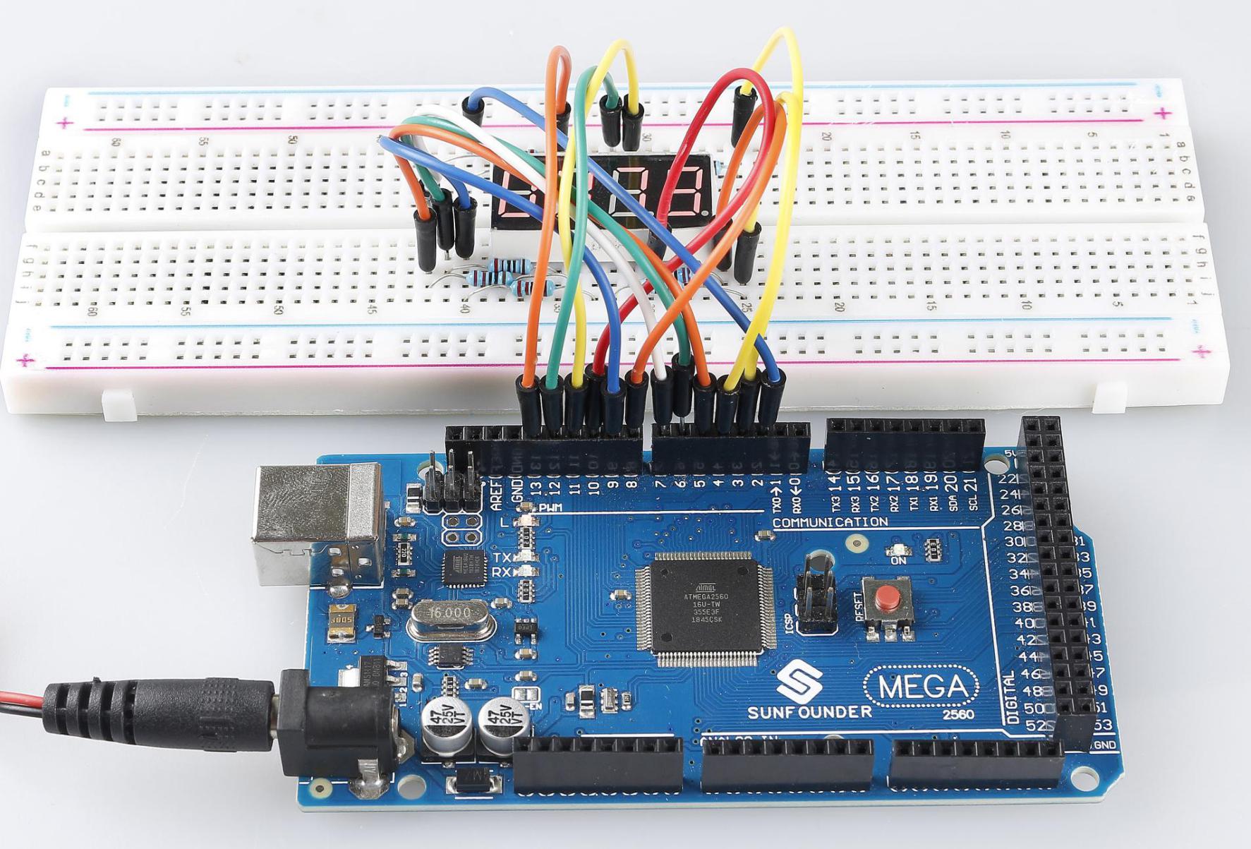
2.7 4-Digital 7-Segment Display
Overview
In this lesson, you will learn about the 4-Digital 7-Segment Display. It consists of four 7-segment displays working together so as to display 4 digit numbers.
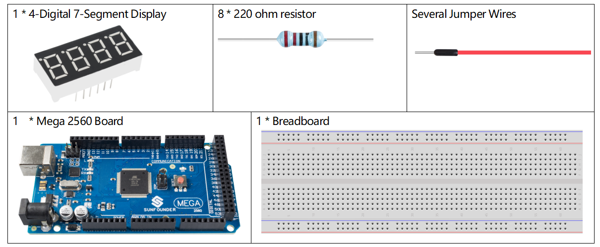
Components Required
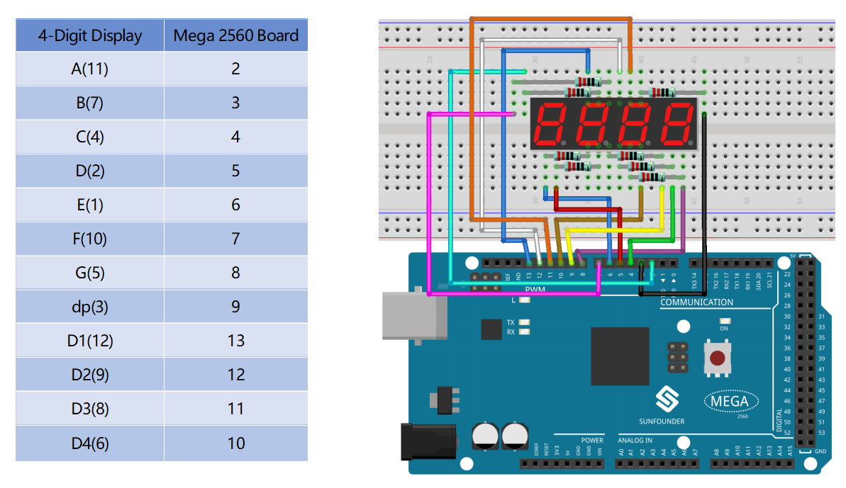
Fritzing Circuit
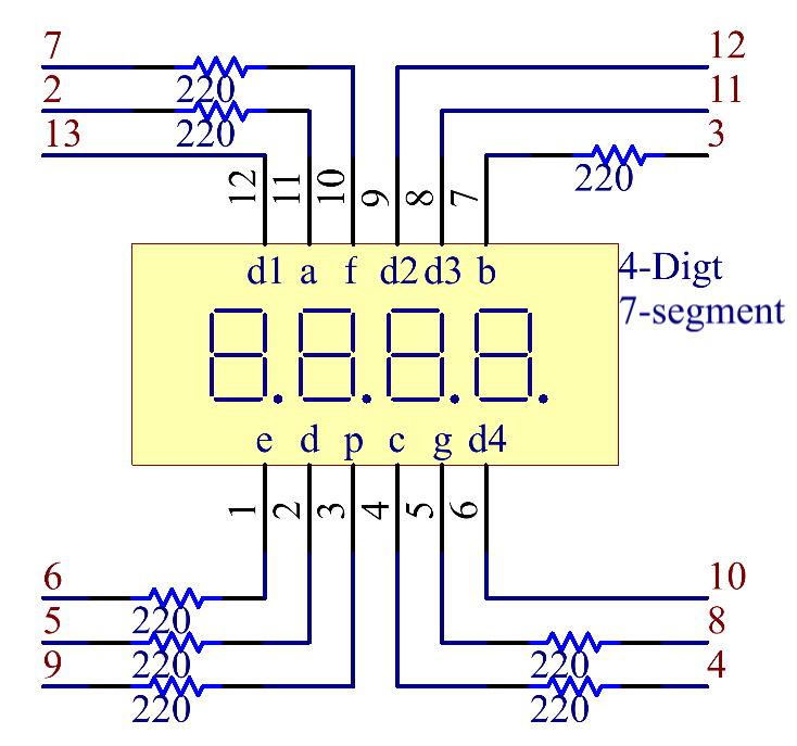
Schematic Diagram
Code
Note
You can open the file
2.7_4digitalSegment.inounder the path ofsunfounder_vincent_kit_for_arduino\code\2.7_4digitalSegmentdirectly.
Code Analysis
In essence, this code uses the principle of multiplexing to display a 4-digit number on a 7-segment display. By rapidly switching between digits and displaying one digit at a time, it gives the illusion of all digits being displayed concurrently.
The stopwatch functionality is achieved by using the built-in millis() function to track time and increment the displayed number every second.
Variable and Constant Definitions:
int segmentPins[] = {2, 3, 4, 5, 6, 7, 8, 9};
int digitPins[] = {13, 12, 11, 10};

long n = 0; // Variable to store the current stopwatch number
int del = 5; // Delay time (in milliseconds) to keep each digit illuminated
unsigned long previousMillis = 0; // Store the last time the stopwatch incremented
const long interval = 1000; // One-second interval (in milliseconds)
segmentPinsanddigitPinsarrays define the pins that are connected to the segments and the digits of the 7-segment display, respectively.nis a long variable that keeps track of the current stopwatch number, starting from 0 and incrementing.delis a delay time to maintain the display of the current digit before transitioning to the next one.previousMillisandintervalare related to timing to decide when to increment the stopwatch.
7-Segment Patterns for Numbers:
The 2D array numbers defines how each of the numbers 0-9 is represented on a common-cathode 7-segment display. Each sub-array has 8 values (either HIGH or LOW), corresponding to the 7 segments and a decimal point. This pattern helps in driving the appropriate segments for each number.
byte numbers[10][8] = {
    {HIGH, HIGH, HIGH, HIGH, HIGH, HIGH, LOW, LOW},  // 0
    {LOW, HIGH, HIGH, LOW, LOW, LOW, LOW, LOW},      // 1
    {HIGH, HIGH, LOW, HIGH, HIGH, LOW, HIGH, LOW},   // 2
    {HIGH, HIGH, HIGH, HIGH, LOW, LOW, HIGH, LOW},   // 3
    {LOW, HIGH, HIGH, LOW, LOW, HIGH, HIGH, LOW},    // 4
    {HIGH, LOW, HIGH, HIGH, LOW, HIGH, HIGH, LOW},   // 5
    {HIGH, LOW, HIGH, HIGH, HIGH, HIGH, HIGH, LOW},  // 6
    {HIGH, HIGH, HIGH, LOW, LOW, LOW, LOW, LOW},     // 7
    {HIGH, HIGH, HIGH, HIGH, HIGH, HIGH, HIGH, LOW}, // 8
    {HIGH, HIGH, HIGH, HIGH, LOW, HIGH, HIGH, LOW}   // 9
};
Setup Function:
void setup() {
    // Configure all segment and digit pins as OUTPUT
    for (int i = 0; i < 8; i++) {
        pinMode(segmentPins[i], OUTPUT);
    }
    for (int i = 0; i < 4; i++) {
        pinMode(digitPins[i], OUTPUT);
        digitalWrite(digitPins[i], HIGH); // Initially turn off all digits (for common-cathode displays, HIGH is OFF)
    }
}
All segment and digit pins are set to OUTPUT mode since they will drive the segments and digits of the display.
Initially, all the digits are turned off, denoted by writing HIGH for a common-cathode display.
Main Loop:
void loop() {
    // Check if a second has passed since the last increment
    if (millis() - previousMillis >= interval) {
        previousMillis += interval; // Update the last increment time
        n = (n + 1) % 10000; // Increment the stopwatch number and wrap around at 9999
    }

    displayNumber(n); // Display the current stopwatch number on the 7-segment display
}
This section checks if the interval (which is set to 1000ms or 1 second) has passed since the last increment of the stopwatch. If so, it increments the number.
The number is then displayed on the 7-segment using the displayNumber() function.
displayNumber()Function:// Function to display a 4-digit number on the 7-segment display void displayNumber(long num) { for (int digit = 0; digit < 4; digit++) { clearLEDs(); // Turn off all segments and digits pickDigit(digit); // Activate the current digit int value = (num / (int)pow(10, 3 - digit)) % 10; // Extract the specific digit from the number pickNumber(value); // Illuminate the segments to display the digit delay(del); // Keep the digit illuminated for a short time } }
This function breaks down the 4-digit number into individual digits and displays each digit one at a time in rapid succession. This creates the illusion of all digits being displayed simultaneously due to persistence of vision.
For each digit, the function first clears all LEDs, selects the appropriate digit using
pickDigit(), and then displays the number on that digit usingpickNumber().The
delay (del)ensures each digit is visible for a short time before transitioning to the next.
pickDigit()Function:This function is responsible for selecting (or turning on) one of the four digits on the 7-segment display. This is achieved by setting the corresponding digit pin to LOW.
void pickDigit(int x) {
    digitalWrite(digitPins[x], LOW); // Turn ON the selected digit (for common-cathode displays, LOW is ON)
}
pickNumber()Function:Given a single number (0-9), this function drives the 7-segment display’s segments to show that number. It uses the previously defined
numbersarray to know which segments to turn on/off.void pickNumber(int x) { for (int i = 0; i < 8; i++) { digitalWrite(segmentPins[i], numbers[x][i]); // Set each segment according to the pattern for the given number } }
clearLEDs()Function:As the name suggests, this function turns off all segments and digits. It’s used to ensure that only one digit is active at a time during the multiplexing process in the
displayNumber()function.void clearLEDs() { for (int i = 0; i < 8; i++) { digitalWrite(segmentPins[i], LOW); // Turn off all segments } for (int i = 0; i < 4; i++) { digitalWrite(digitPins[i], HIGH); // Turn off all digits } }
Phenomenon Picture