Note
Hello, welcome to the SunFounder Raspberry Pi & Arduino & ESP32 Enthusiasts Community on Facebook! Dive deeper into Raspberry Pi, Arduino, and ESP32 with fellow enthusiasts.
Why Join?
Expert Support: Solve post-sale issues and technical challenges with help from our community and team.
Learn & Share: Exchange tips and tutorials to enhance your skills.
Exclusive Previews: Get early access to new product announcements and sneak peeks.
Special Discounts: Enjoy exclusive discounts on our newest products.
Festive Promotions and Giveaways: Take part in giveaways and holiday promotions.
👉 Ready to explore and create with us? Click [here] and join today!
1.7 Analog Input Control Output
Overview
You can install an I/O system by using an analog input/ output device. For example, you can use potentiometer, photoresistor, water level sensor, etc., to control the brightness of LED, the speed of motor, and the like. In this lesson, potentiometer and LED are taken as examples to change the brightness of the LED when the potentiometer is turning.
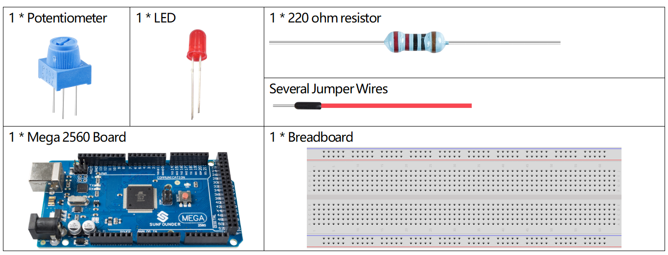
Components Required
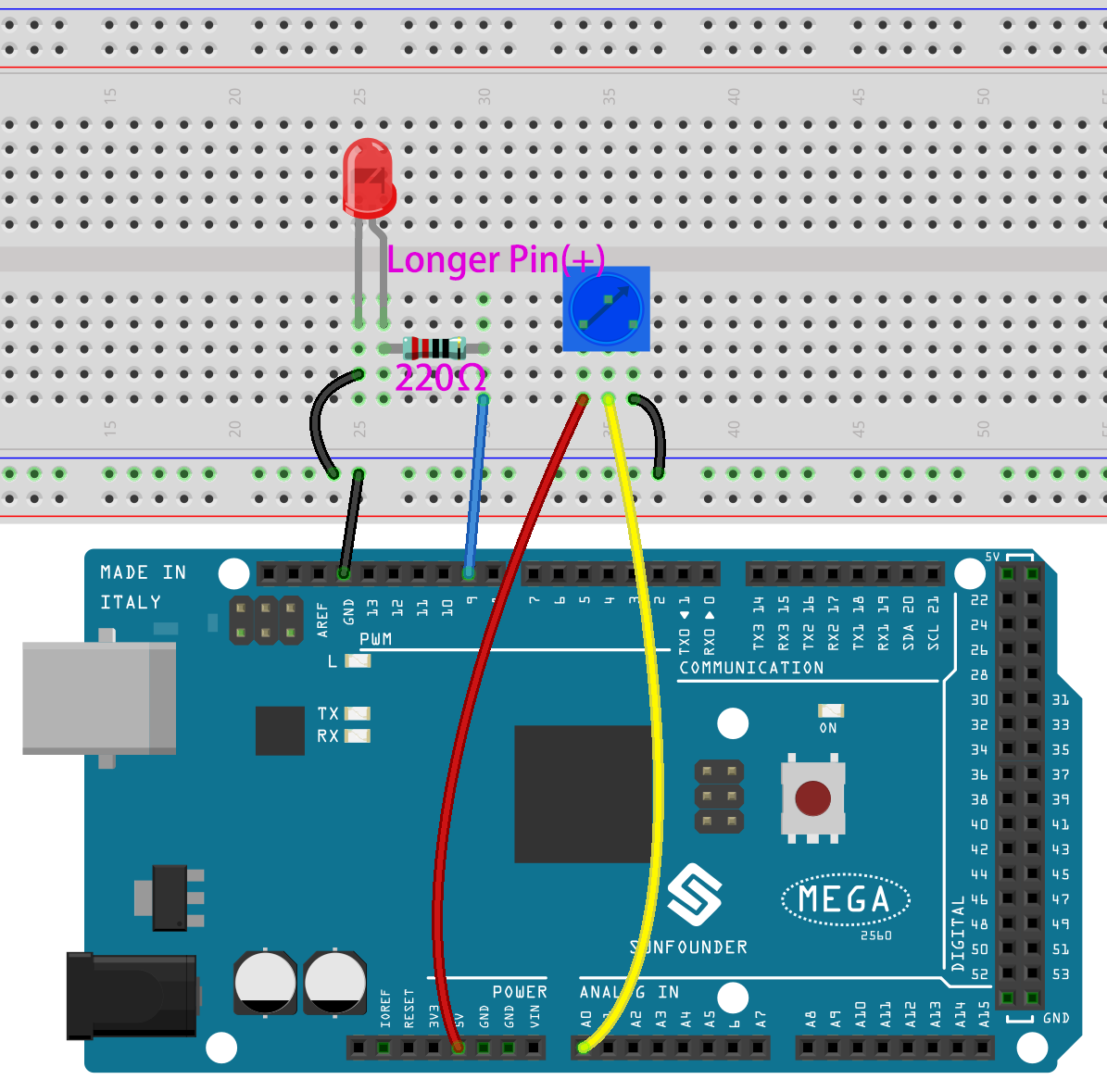
Fritzing Circuit
In this lesson, we use PWM pin 9 to drive LED. The analog pin (A0) is used to read the value of potentiometer. After uploading the code, you’ll notice that the brightness of the LED changes as the potentiometer rotates.
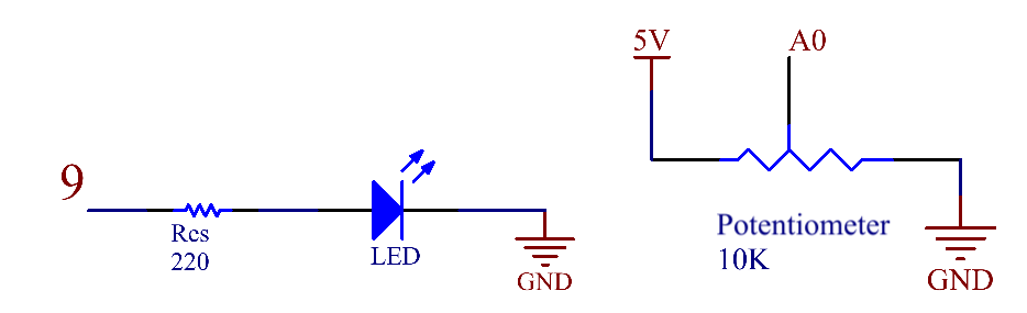
Schematic Diagram
Code
Note
You can open the file
1.7_analogInputControlOutput.inounder the path ofsunfounder_vincent_kit_for_arduino\code\1.7_analogInputControlOutputdirectly.Or copy this code into Arduino IDE.
When the codes are uploaded to the Mega2560 board, you can see that the brightness of LED is changing with the turning of the knob of potentiometer.
Code Analysis
Declare the pins of LED and Button.
const int sensorPin = A0;
const int ledPin = 9;
In setup(), set the mode of ledPin to OUTPUT.
pinMode(ledPin,OUTPUT);
Read the readings of potentiometer in loop().
int sensorValue=analogRead(sensorPin);
Map the potentiometer reading to the LED brightness value (0-1024 is mapped to 0-255).
int brightness = map(sensorValue,0,1024,0,255);
Write the brightness value to LED.
analogWrite(ledPin,brightness);
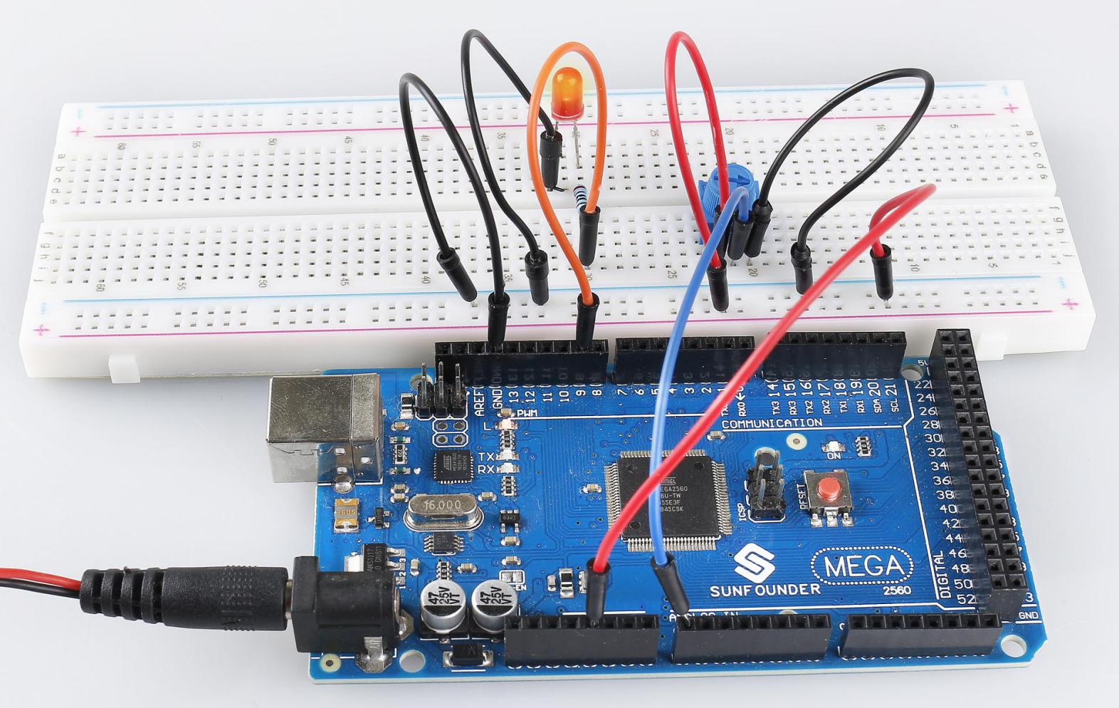
Phenomenon Picture