Note
Hello, welcome to the SunFounder Raspberry Pi & Arduino & ESP32 Enthusiasts Community on Facebook! Dive deeper into Raspberry Pi, Arduino, and ESP32 with fellow enthusiasts.
Why Join?
Expert Support: Solve post-sale issues and technical challenges with help from our community and team.
Learn & Share: Exchange tips and tutorials to enhance your skills.
Exclusive Previews: Get early access to new product announcements and sneak peeks.
Special Discounts: Enjoy exclusive discounts on our newest products.
Festive Promotions and Giveaways: Take part in giveaways and holiday promotions.
👉 Ready to explore and create with us? Click [here] and join today!
2.30 IR Obstacle Avoidance Sensor
Overview
In this lesson, you will learn how to use IR Obstacle Avoidance Sensor. This module is commonly installed on the car and robot to judge the existence of the obstacles ahead. Also it is widely used in hand held device, water faucet and so on.
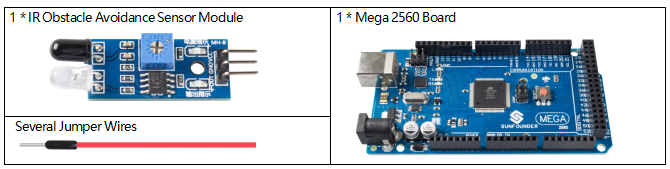
Components Required
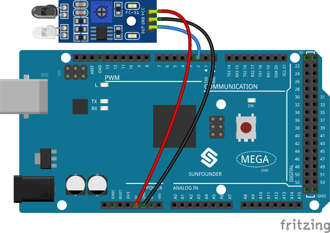
Fritzing Circuit
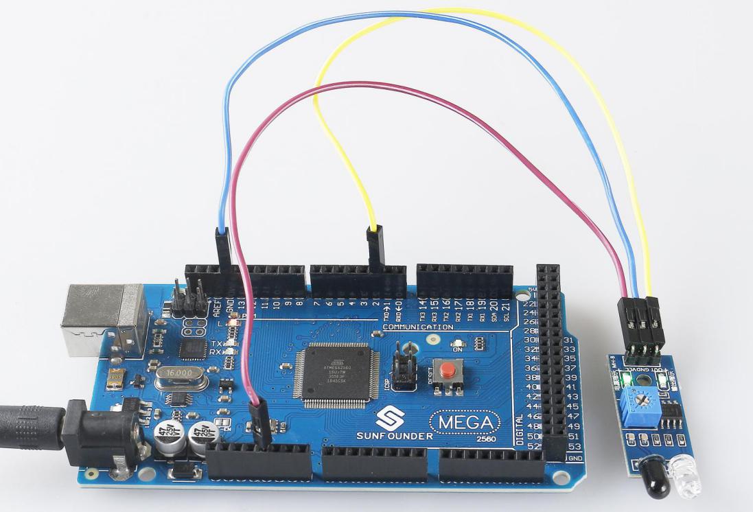
We can directly connect the pins of IR Obstacle Sensor Module with the pins of Mega 2560 Board. The digital pin 2 is used to read the signal of IR Obstacle Avoidance Sensor Module. We get the VCC of IR Sensor Module connected to 5V, GND to GND, OUT to digital pin 2.
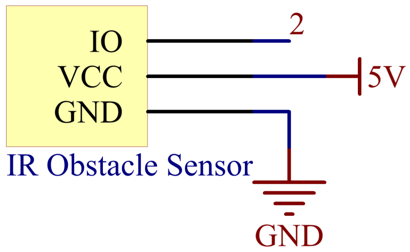
Schematic Diagram
Code
Note
You can open the file
2.30_irSensorModule.inounder the path ofsunfounder_vincent_kit_for_arduino\code\2.30_irSensorModuledirectly.Or copy this code into Arduino IDE.
Uploaded the codes to the Mega2560 board, you can see the readings of pins on the serial monitor. When IR Obstacle Avoidance Sensor Module detects there is something covering ahead, there appears 「0」on the serial monitor; otherwise,「1」is displayed. Refer to:ref:ar_digital_read to check the detail code explanation.
Phenomenon Picture