Note
Hello, welcome to the SunFounder Raspberry Pi & Arduino & ESP32 Enthusiasts Community on Facebook! Dive deeper into Raspberry Pi, Arduino, and ESP32 with fellow enthusiasts.
Why Join?
Expert Support: Solve post-sale issues and technical challenges with help from our community and team.
Learn & Share: Exchange tips and tutorials to enhance your skills.
Exclusive Previews: Get early access to new product announcements and sneak peeks.
Special Discounts: Enjoy exclusive discounts on our newest products.
Festive Promotions and Giveaways: Take part in giveaways and holiday promotions.
👉 Ready to explore and create with us? Click [here] and join today!
1.2 Digital Write
Overview
The digitalWrite() statement here is used to write high level or low level to pins and to let LED and active buzzer 「work 」or 「stop」. In this lesson, we will take LED as an example to introduce the experiment phenomenon.
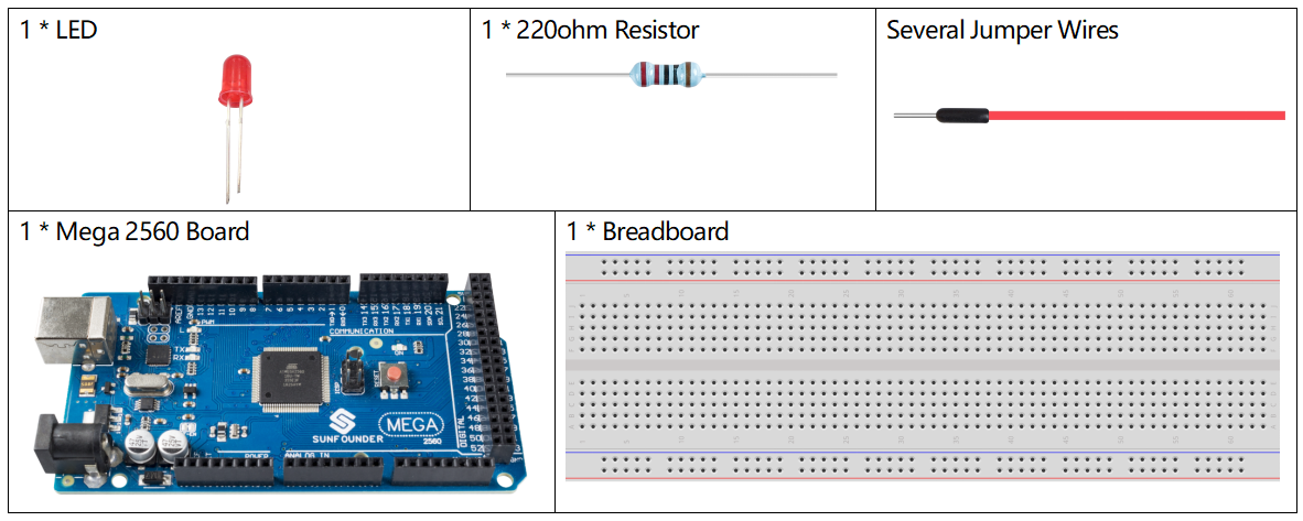
Components Required
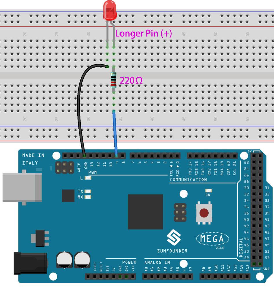
Fritzing Circuit
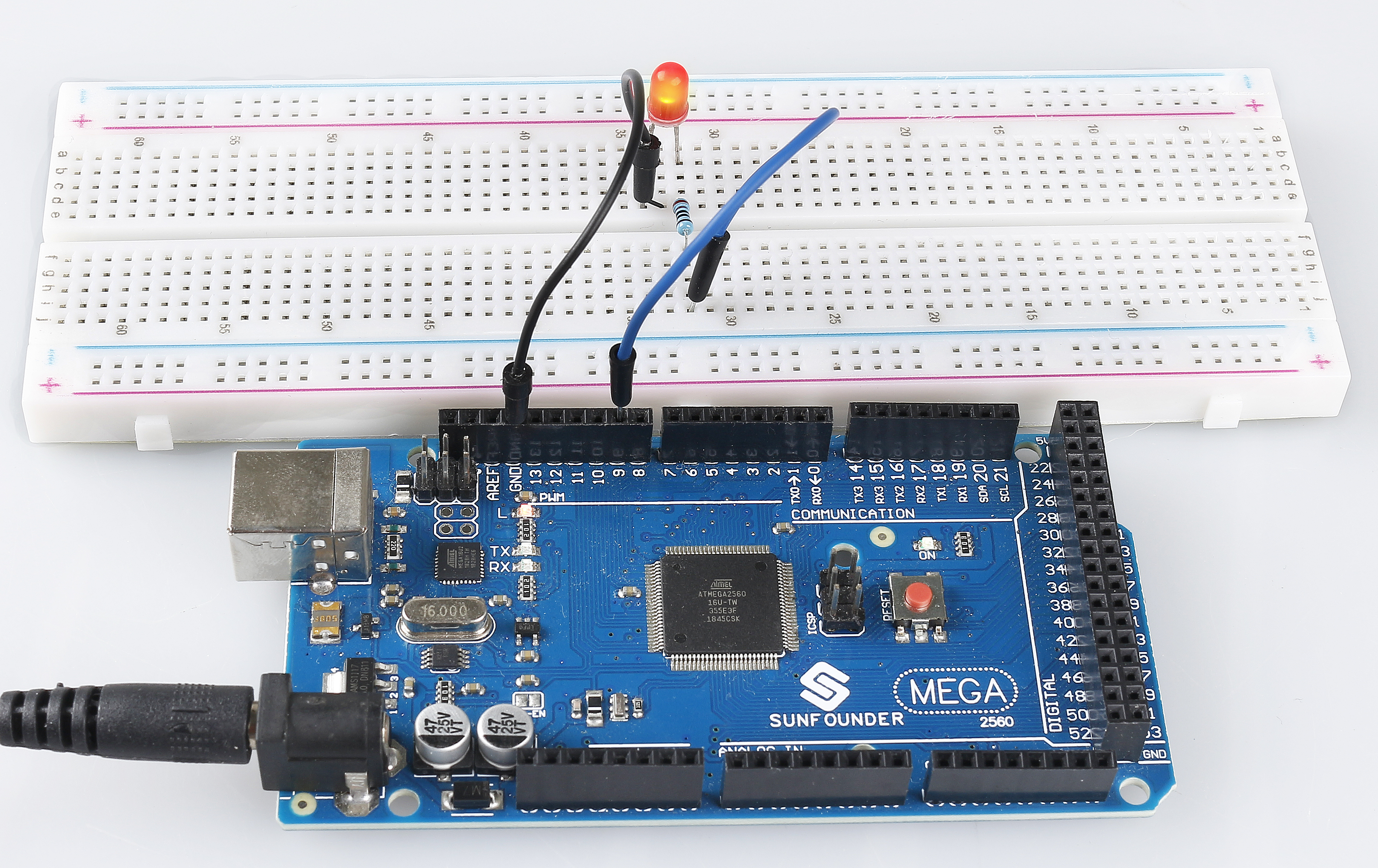
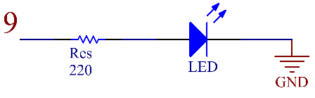
In this example, we use digital pin 9 to drive the LED. Attach one side of the resistor to the digital pin 9 and the longer pin (anode) of the LED to the other side of the resistor. Connect the shorter pin (cathode) of the LED to GND.
Schematic Diagram
Code
After finishing the circuit connection, connect the Mega2560 board to the computer. Run the Arduino software IDE and type in the following codes.
Note
You can open the file
1.2_digitalWrite.inounder the path ofsunfounder_vincent_kit_for_arduino\code\1.2_digitalWritedirectly.Or copy this code into Arduino IDE.
Upload the codes to the Mega2560 board, and you can see the blinking of LED.
Code Analysis
Here, we connect the LED to the digital pin 9, so we need to declare an int variable called ledpin at the beginning of the program and assign a value of 9.
const int ledPin = 9;
Now, initialize the pin in the setup() function, where you need to initialize the pin to OUTPUT mode.
pinMode(ledPin, OUTPUT);
In loop(), digitalWrite() is used to provide 5V high level signal for ledpin, which will cause voltage difference between LED pins and light LED up.
digitalWrite(ledPin, HIGH);
If the level signal is changed to LOW, the ledPin’s signal will be returned to 0 V to turn LED off.
digitalWrite(ledPin, LOW);
An interval between on and off is required to allow people to see the change, so we use a delay(1000) code to let the controller do nothing for 1000 ms.
delay(1000);
Phenomenon Picture