Note
Hello, welcome to the SunFounder Raspberry Pi & Arduino & ESP32 Enthusiasts Community on Facebook! Dive deeper into Raspberry Pi, Arduino, and ESP32 with fellow enthusiasts.
Why Join?
Expert Support: Solve post-sale issues and technical challenges with help from our community and team.
Learn & Share: Exchange tips and tutorials to enhance your skills.
Exclusive Previews: Get early access to new product announcements and sneak peeks.
Special Discounts: Enjoy exclusive discounts on our newest products.
Festive Promotions and Giveaways: Take part in giveaways and holiday promotions.
👉 Ready to explore and create with us? Click [here] and join today!
2.4 LED Bar Graph
Overview
In this lesson, you will learn something about LED Bar Graph. Generally, LED Bar Graph works as a battery level indicator, Audio equipment, industrial control panel. If we want, we can also find its other application.
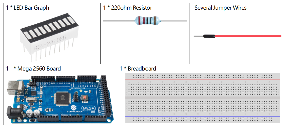
Components Required
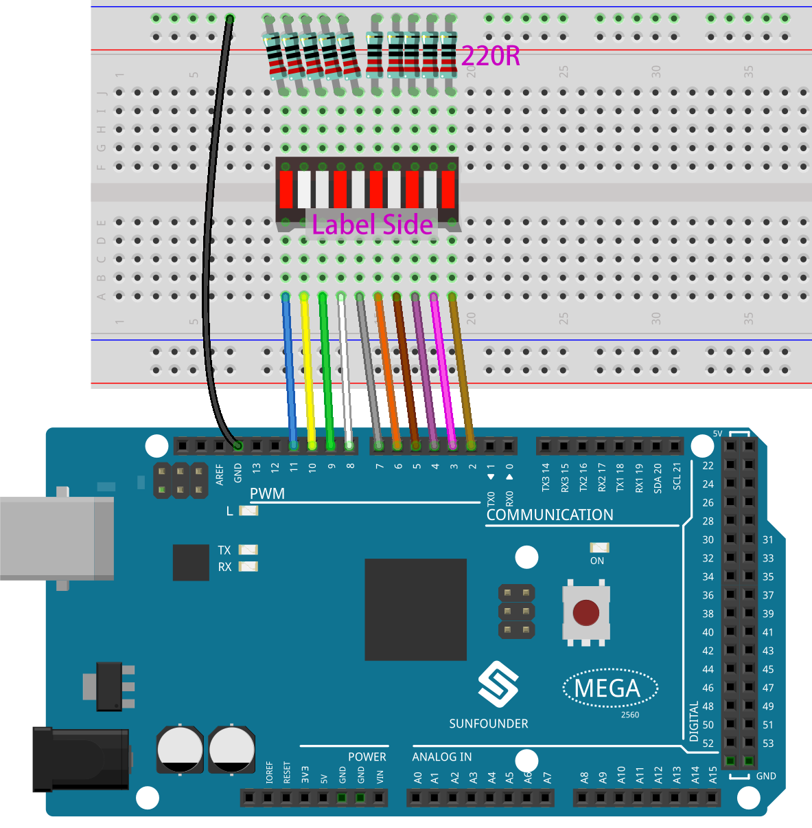
Fritzing Circuit
In this example, we use digital pins 2~11 to drive the LED Bar Graph. LED Bar Graph has ten separate LEDs inside and each LED has two pins. The left pins 1~10 of LED Bar Graph are connected with the digital pins 2~11 respectively; the right side pins 11~20 are separately extended to same side of these 220ohm resistors whose other sides are identically connected to GND.
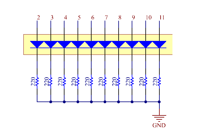
Schematic Diagram
Code
Note
You can open the file
2.4_ledBarGraph.inounder the path ofsunfounder_vincent_kit_for_arduino\code\2.4_ledBarGraphdirectly.Or copy this code into Arduino IDE.
Uploaded the codes to the Mega2560 board, you can see that the LEDs on the LED Bar Graph flash in sequence.
Code Analysis
The codes in setup() use the for loop to initialize pins 2~11 to output mode in turn.
for(int i=2;i<=11;i++)
{
    pinMode(i,OUTPUT);
}
The for loop is used in loop() to make the LED flash(turn on 0.5s, then turn off 0.5s) in sequence.
for(int i=2;i<=11;i++)
{
    digitalWrite(i,HIGH);
    delay(500);
digitalWrite(i,LOW);
    delay(500);
}
Refer to Part 1-1.2 Digital Write for more details about controlling the LED by using digital pins.
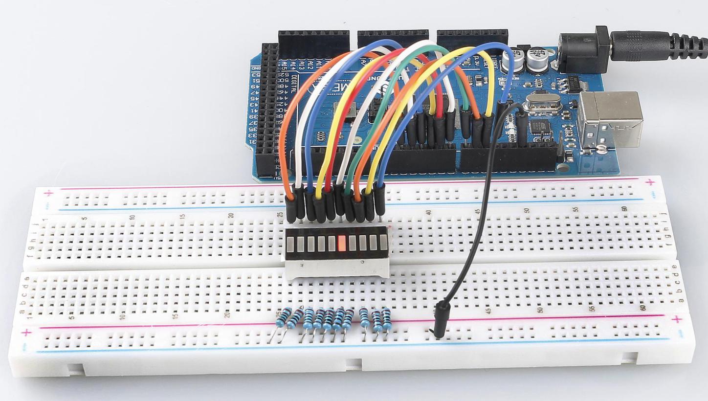
Phenomenon Picture