Note
Hello, welcome to the SunFounder Raspberry Pi & Arduino & ESP32 Enthusiasts Community on Facebook! Dive deeper into Raspberry Pi, Arduino, and ESP32 with fellow enthusiasts.
Why Join?
Expert Support: Solve post-sale issues and technical challenges with help from our community and team.
Learn & Share: Exchange tips and tutorials to enhance your skills.
Exclusive Previews: Get early access to new product announcements and sneak peeks.
Special Discounts: Enjoy exclusive discounts on our newest products.
Festive Promotions and Giveaways: Take part in giveaways and holiday promotions.
👉 Ready to explore and create with us? Click [here] and join today!
2.28 Sound Sensor Module
Overview
In this lesson, you will learn how to use a sound sensor module. The sound sensor module provides an easy way to detect sound and is generally used for detecting sound intensity.
Components Required
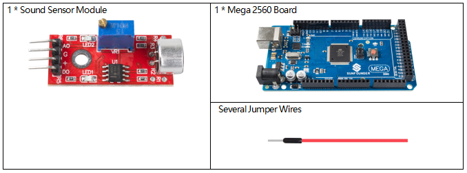
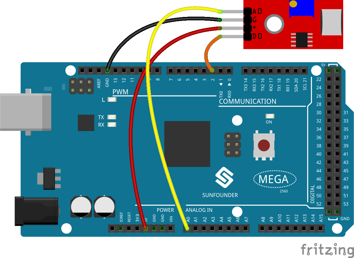
Fritzing Circuit
In this example, we can directly connect the pin of Sound Sensor Module to the pin of Mega 2560 Board, connect the pin「G」 of Sound Sensor Module to GND, the pin 「+」to 5V, AO to analog pin A0, and D0 to digital pin 2.
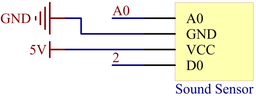
Schematic Diagram
Code
Note
You can open the file
2.28_soundSensorModule.inounder the path ofsunfounder_vincent_kit_for_arduino\code\2.28_soundSensorModuledirectly.Or copy this code into Arduino IDE.
After uploading the code to the Mega2560 board, you can open the serial monitor to see the read value of the pin. When the ambient sound gets louder, the digital reading is 「1」 (adjust the potentiometer of the module to modify the threshold to trigger the high level), and the reading value of the analog pin will change significantly; when the environment is quiet, the digital reading is 「0」 and the analog reading changes smoothly.
The range of analog reading is「0」~「1023」, but influenced by the the environmental condition and the characteristics of sound sensor, the actual reading range may be smaller than the theoretical one. If an oscilloscope is used, the changing of analog reading of the sound sensor will be more obvious.
About the detail code explanation, refer to 1.5 Analog Read and 1.4 Digital Read.
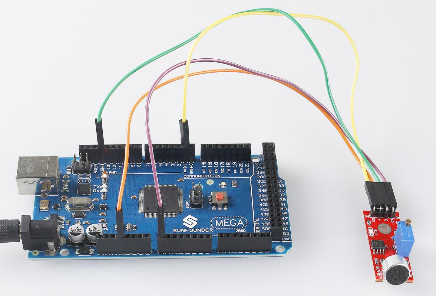
Phenomenon Picture