Note
Hello, welcome to the SunFounder Raspberry Pi & Arduino & ESP32 Enthusiasts Community on Facebook! Dive deeper into Raspberry Pi, Arduino, and ESP32 with fellow enthusiasts.
Why Join?
Expert Support: Solve post-sale issues and technical challenges with help from our community and team.
Learn & Share: Exchange tips and tutorials to enhance your skills.
Exclusive Previews: Get early access to new product announcements and sneak peeks.
Special Discounts: Enjoy exclusive discounts on our newest products.
Festive Promotions and Giveaways: Take part in giveaways and holiday promotions.
👉 Ready to explore and create with us? Click [here] and join today!
2.34 MPU6050 Module
Overview
In this lesson, you will learn how to use MPU6050. MPU-6050 is a 6-axis (combined 3-axis Gyroscope, 3-axis Accelerometer) motion tracking devices. It is often used for augmented reality and electronic image stabilization (EIS: Electronic Image Stabilization), optical image stabilization (OIS: Optical Image Stabilization), “Zero touch” gesture user interface.
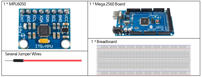
Components Required
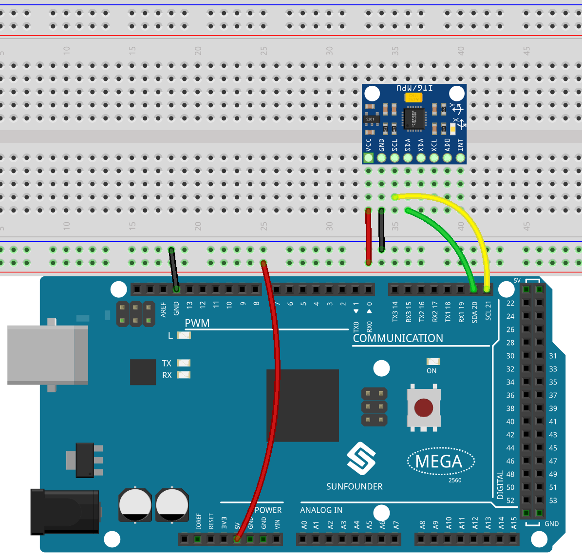
Fritzing Circuit
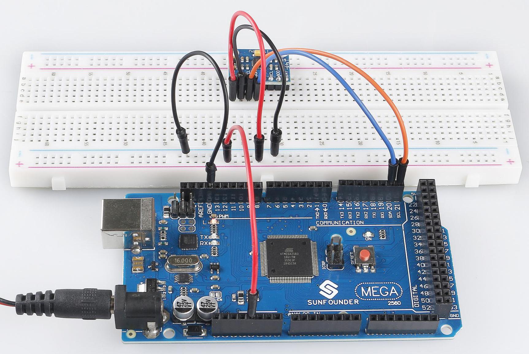
In this example, we drive MPU6050 with IIC. We inset MPU6050 into the breadboard; get the VCC connected to 5V, GND to GND, SCL to pin SCL 21, and SDA to the pin SDA 20.
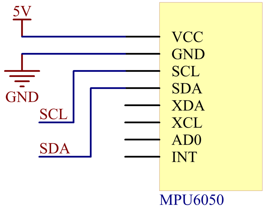
Schematic Diagram
Code
Note
You can open the file
2.34_MPU6050.inounder the path ofsunfounder_vincent_kit_for_arduino\code\2.34_MPU6050directly.Or copy this code into Arduino IDE.
After uploading the codes to the Mega2560 board, you can open the serial monitor to see the gravity acceleration and angular velocity of MPU6050 in each direction.
Code Analysis
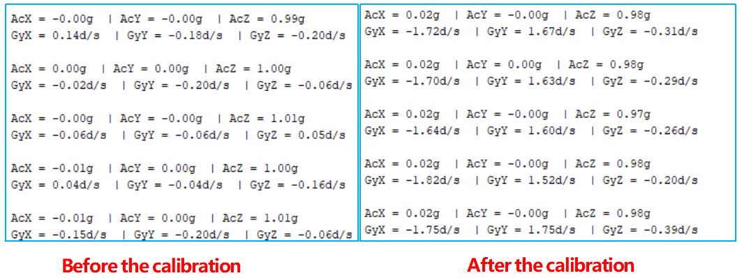
In the stationary desktop state, the Z-axis acceleration is 1 gravity unit, and the X and Y axes are 0.
Before your use, you need to calibrate the module, the methods are as follows:
MPU6050 modules are placed horizontally on the desktop and then you can fix them with clamps or adhesive tape.
Run the sample codes to get the RAW DATA of MPU6050 when it is static.
Add compensation according to the readings when MPU6050 is static.
Take MPU6050 we use as an example, and the results of compensation are as follows:
Serial.print(AcX / 65536  * ACCELE_RANGE - 0.02);
Serial.print(AcY / 65536  * ACCELE_RANGE + 0);
Serial.print(AcZ/65536  * ACCELE_RANGE + 0.02);
Serial.print(GyX / 65536  * GYROSC_RANGE + 1.70);
Serial.print(GyY/65536  * GYROSC_RANGE - 1.70);
Serial.print(GyZ/65536*GYROSC_RANGE + 0.25);
Phenomenon Picture