Note
Hello, welcome to the SunFounder Raspberry Pi & Arduino & ESP32 Enthusiasts Community on Facebook! Dive deeper into Raspberry Pi, Arduino, and ESP32 with fellow enthusiasts.
Why Join?
Expert Support: Solve post-sale issues and technical challenges with help from our community and team.
Learn & Share: Exchange tips and tutorials to enhance your skills.
Exclusive Previews: Get early access to new product announcements and sneak peeks.
Special Discounts: Enjoy exclusive discounts on our newest products.
Festive Promotions and Giveaways: Take part in giveaways and holiday promotions.
👉 Ready to explore and create with us? Click [here] and join today!
2.15 Button
Overview
In this lesson, you will learn about Button. Button is a common component used to control electronic devices. It is usually used as a switch to connect or break circuits.
Components Required
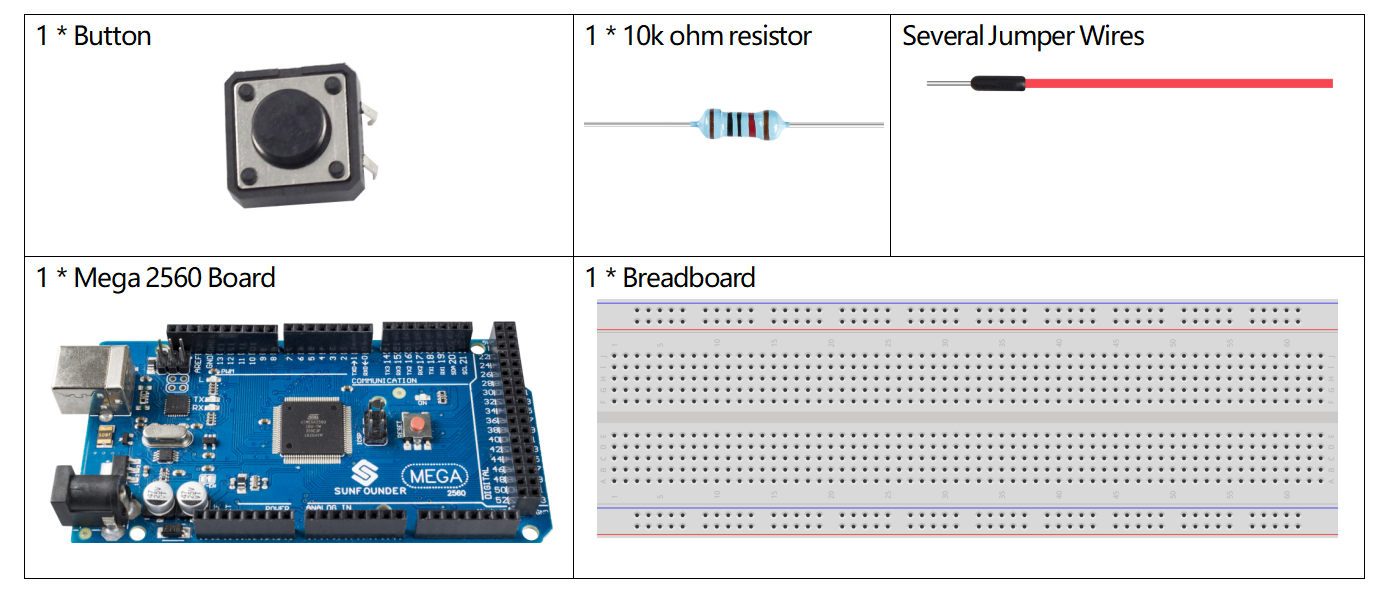
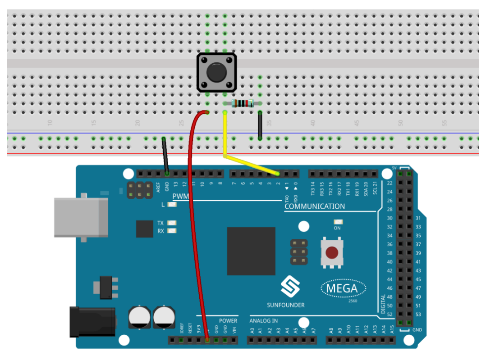
Fritzing Circuit
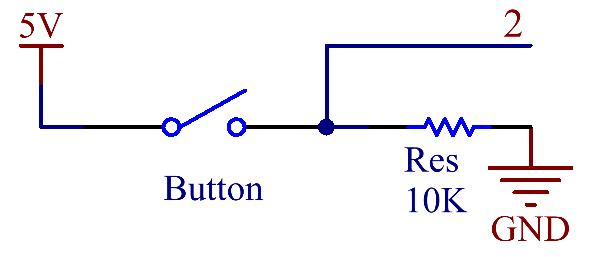
In this example, we read the signal of the button with the digital pin. When the button is not pressed, the digital pin 2 (through the drop-down resistor) is connected to ground to read the low level (0); when the button is pressed, the two pins are connected and when the pin is connected to the 5V power supply, the high level (1) is read.
Note
If you disconnect the digital I/O pin from anything, the LED may blink erratically. The input is “floating” or it doesn’t have a solid connection to voltage or ground, so it will randomly return either HIGH or LOW. That’s why there needs a pull-down resistor in the circuit.
Schematic Diagram
Code
Example 1:
Note
You can open the file
2.15_button.inounder the path ofsunfounder_vincent_kit_for_arduino\code\2.15_buttondirectly.Or copy this code into Arduino IDE.
Uploaded the codes to the Mega2560 board, you can see the readings of the pins on the serial monitor. When you press down the Button, there will display 「1」on the serial monitor, and once you release it, there will display「0」. As for the detail code explanation, please refer to 1.4 Digital Read.
Example 2:
Note
You can open the file
2.15_button_2.inounder the path ofsunfounder_vincent_kit_for_arduino\code\2.15_button_2directly.Or copy this code into Arduino IDE.
Uploaded the codes to the Mega2560 board, every time you press the button, the output value will switch between 0 and 1. If you want to know more about the code explanation, you can turn to 1.10 State Change Detection.
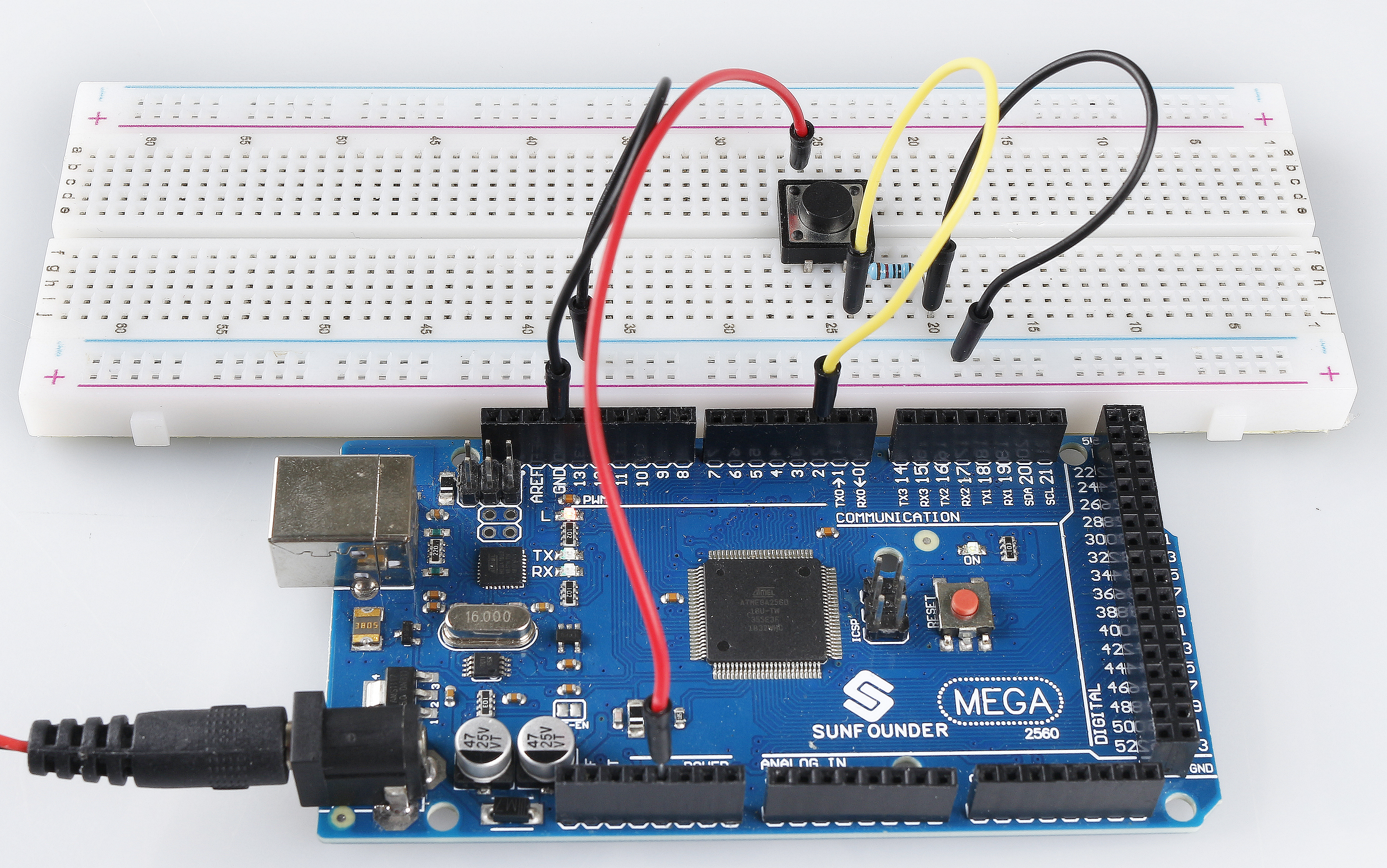
Phenomenon Picture