Note
Hello, welcome to the SunFounder Raspberry Pi & Arduino & ESP32 Enthusiasts Community on Facebook! Dive deeper into Raspberry Pi, Arduino, and ESP32 with fellow enthusiasts.
Why Join?
Expert Support: Solve post-sale issues and technical challenges with help from our community and team.
Learn & Share: Exchange tips and tutorials to enhance your skills.
Exclusive Previews: Get early access to new product announcements and sneak peeks.
Special Discounts: Enjoy exclusive discounts on our newest products.
Festive Promotions and Giveaways: Take part in giveaways and holiday promotions.
👉 Ready to explore and create with us? Click [here] and join today!
2.6 74HC595
Overview
In this lesson, you will learn how to use 74HC595. 74HC595 consists of an 8−bit shift register and a storage register with three−state parallel outputs. It converts serial input into parallel output so you can save IO ports of an MCU.
Components Required
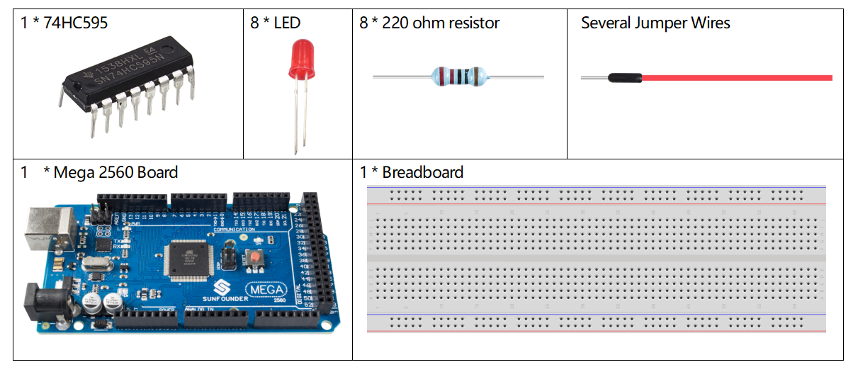
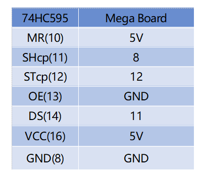
Fritzing Circuit
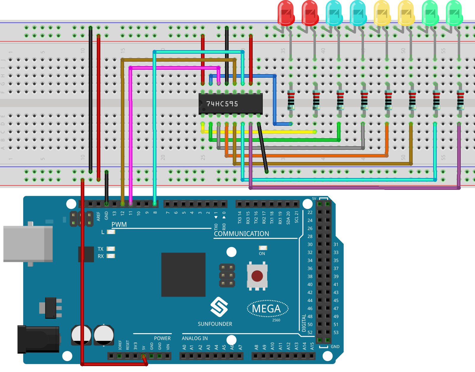
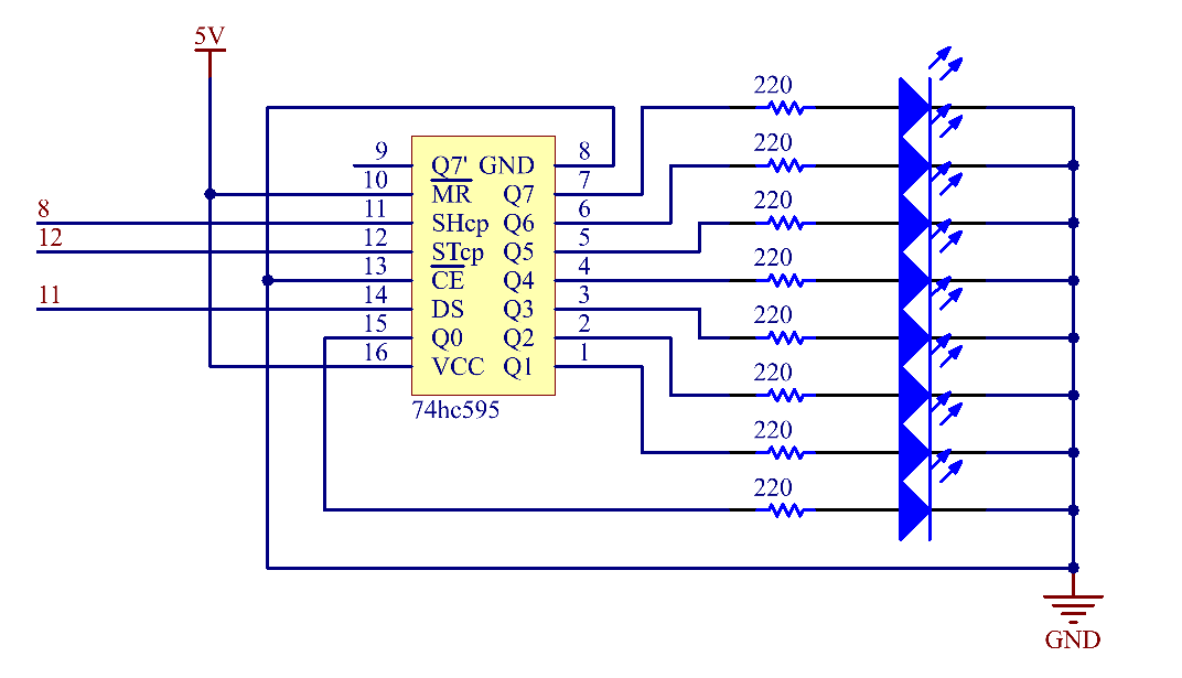
In this example, we use 74HC595 to control LED. Give each data output pin(Q0-Q7)a 220 ohm resistor then connect them to LED. The wiring diagram is as follows:
Schematic Diagram
Code
Note
You can open the file
2.6_74HC595.inounder the path ofsunfounder_vincent_kit_for_arduino\code\2.6_74HC595directly.Or copy this code into Arduino IDE.
When you finish uploading the codes to the Mega2560 board, you can see the LEDs turning on one after another.
Code Analysis
Declare an array, store several 8 bit binary numbers that are used to change the working state of the eight LEDs controlled by 74HC595.
int datArray[] = {B00000000, B00000001, B00000011, B00000111, B00001111, B00011111, B00111111, B01111111, B11111111};
Set STcp to low level first and then high level. It will generate a rising edge pulse of STcp.
digitalWrite(STcp,LOW);
shiftOut() is used to shift out a byte of data one bit at a time, which means to shift a byte of data in datArray[num] to the shifting register with the DS pin. MSBFIRST means to move from high bits.
shiftOut(DS,SHcp,MSBFIRST,datArray[num]);
After digitalWrite(STcp,HIGH) is run, the STcp will be at the rising edge. At this time, the data in the shift register will be moved to the memory register.
digitalWrite(STcp,HIGH);
A byte of data will be transferred into the memory register after 8 times. Then the data of memory register are output to the bus (Q0-Q7). For example, shiftout「B00000001」will light up the LED controlled by Q0 and turn off the LED controlled by Q1~Q7.
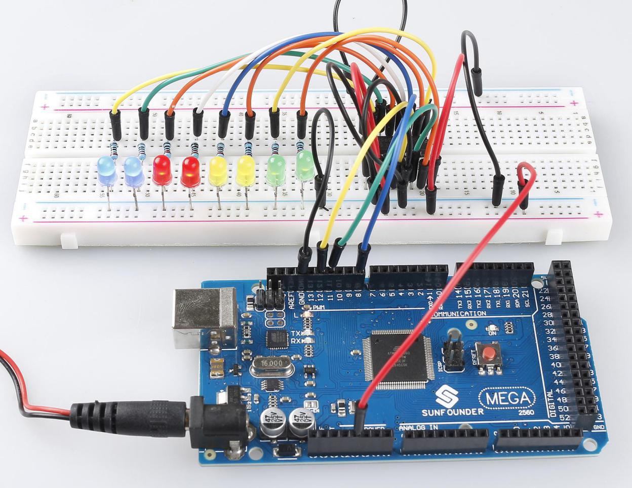
Phenomenon Picture