Note
Hello, welcome to the SunFounder Raspberry Pi & Arduino & ESP32 Enthusiasts Community on Facebook! Dive deeper into Raspberry Pi, Arduino, and ESP32 with fellow enthusiasts.
Why Join?
Expert Support: Solve post-sale issues and technical challenges with help from our community and team.
Learn & Share: Exchange tips and tutorials to enhance your skills.
Exclusive Previews: Get early access to new product announcements and sneak peeks.
Special Discounts: Enjoy exclusive discounts on our newest products.
Festive Promotions and Giveaways: Take part in giveaways and holiday promotions.
👉 Ready to explore and create with us? Click [here] and join today!
2.3 RGB LED
Overview
In this lesson, you will learn about how to use RGB LED. A RGB LED packages three LEDs in red, green and blue into one transparent or semitransparent plastic shell. It displays a broad array of colors by changing the input voltage of three pins and adding the three colors together in different ways. As is said in a statistic, RGB LED can create 16,777,216 different colors.
Components Required

Fritzing Circuit
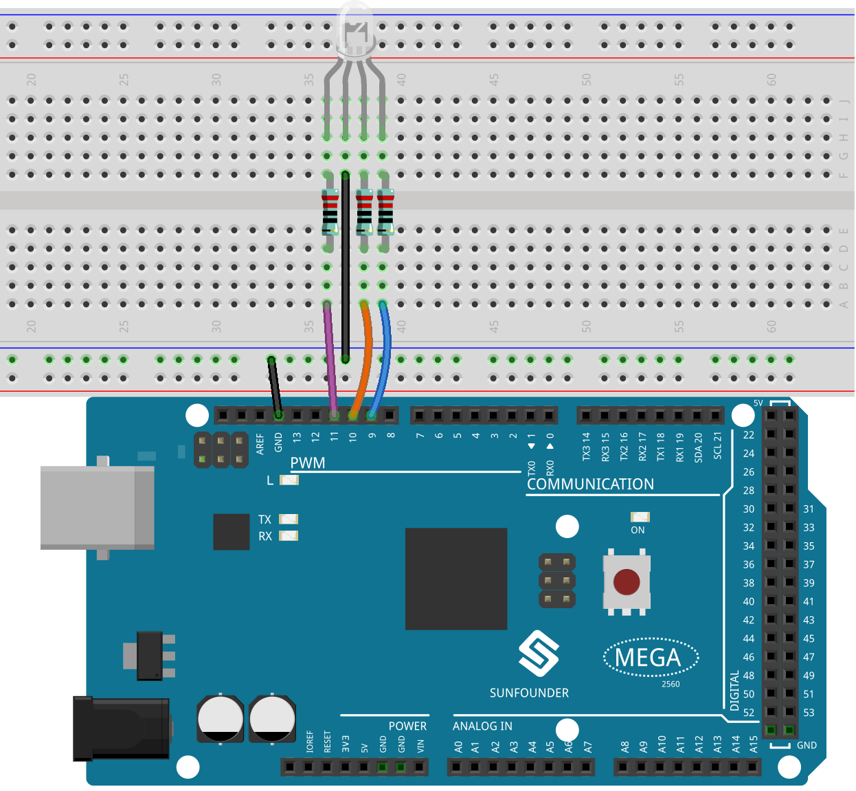
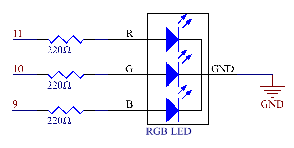
Here we input a value between 0 and 255 to the three pins of the RGB LED to make it display different colors. After connecting the pins of R, G, and B to a current limiting resistor, connect them to the pin 9, pin 10, and pin 11 respectively. The longest pin (GND) of the LED connects to the GND of the Mega 2560. When the three pins are given different PWM values, the RGB LED will display different colors.
Schematic Diagram
Code
Note
You can open the file
2.3_rgbLed.inounder the path ofsunfounder_vincent_kit_for_arduino\code\2.3_rgbLeddirectly.Or copy this code into Arduino IDE.
Code Analysis
In this example, the function used to assign values to the three pins of RGB is packaged in an independent subfunction color().
void color (unsigned char red, unsigned char green, unsigned char blue)// the color generating function
{
analogWrite(redPin, red);
analogWrite(greenPin, green);
analogWrite(bluePin, blue);
}
In loop(), RGB value works as an input argument to call the function color() to realize that the RGB can emit different colors.
void loop()  // run over and over again
{
color(255, 0, 0); // turn the RGB LED red
delay(1000); // delay for 1 second
color(0,255, 0); // turn the RGB LED green
delay(1000); // delay for 1 second
color(0, 0, 255); // turn the RGB LED blue
delay(1000); // delay for 1 second
// ...
}
Phenomenon Picture