Note
Hello, welcome to the SunFounder Raspberry Pi & Arduino & ESP32 Enthusiasts Community on Facebook! Dive deeper into Raspberry Pi, Arduino, and ESP32 with fellow enthusiasts.
Why Join?
Expert Support: Solve post-sale issues and technical challenges with help from our community and team.
Learn & Share: Exchange tips and tutorials to enhance your skills.
Exclusive Previews: Get early access to new product announcements and sneak peeks.
Special Discounts: Enjoy exclusive discounts on our newest products.
Festive Promotions and Giveaways: Take part in giveaways and holiday promotions.
👉 Ready to explore and create with us? Click [here] and join today!
2.22 Potentiometer
Overview
In this lesson, you will learn about Potentiometer. Potentiometer is a resistor component with 3 terminals and its resistance value can be adjusted according to some regular variation.
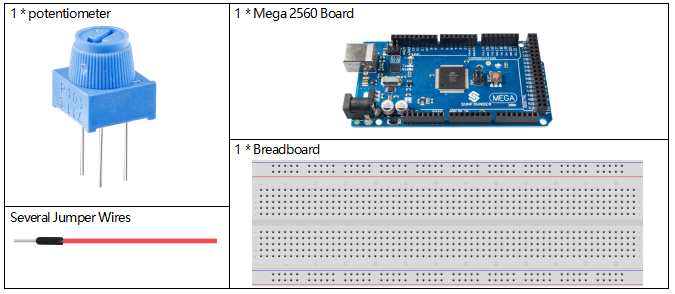
Components Required
Fritzing Circuit
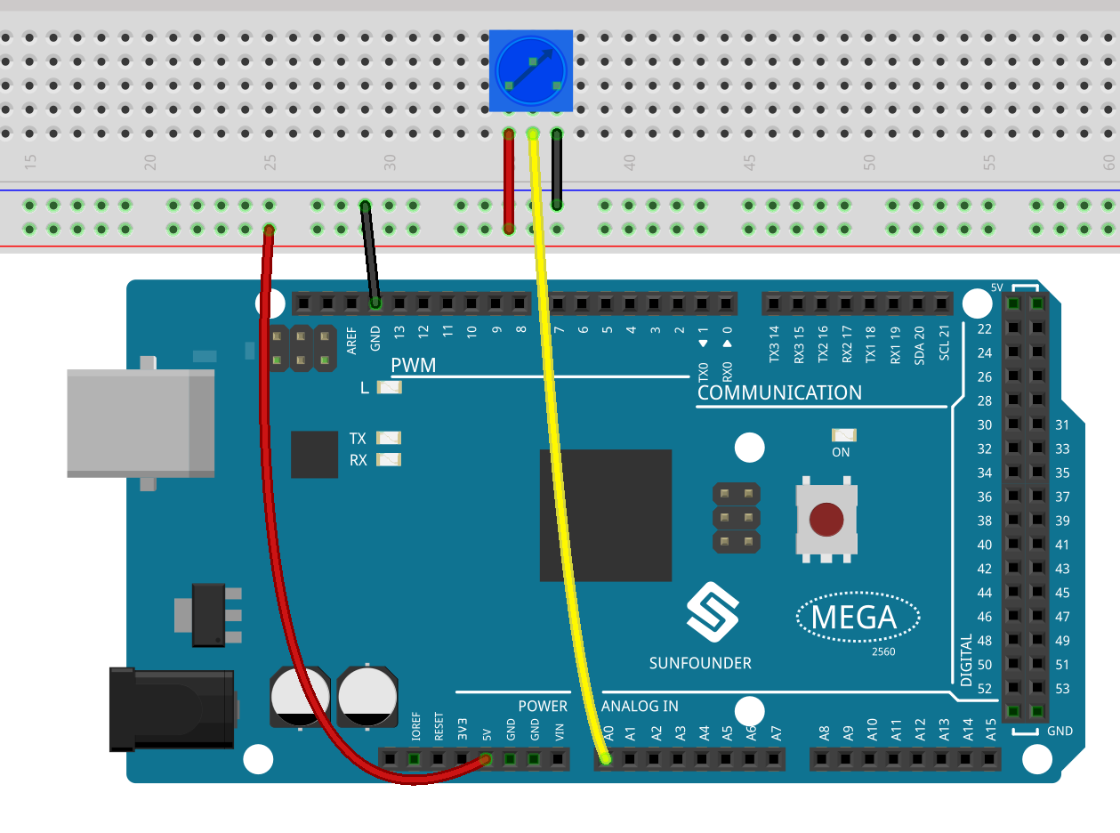
In this example, we use the analog pin (A0) to read the value of the potentiometer. By rotating the axis of the potentiometer, you can change the distribution of resistance among these three pins, changing the voltage on the middle pin. When the resistance between the middle and a outside pin connected to 5V is close to zero (and the resistance between the middle and the other outside pin is close to 10kΩ), the voltage at the middle pin is close to 5 V. The reverse operation (the resistance between the middle and a outside pin connected to 5V is close to 10kΩ) will make the voltage at the middle pin be close to 0V.
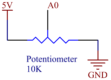
Schematic Diagram
Code
Note
You can open the file
2.22_potentiometer.inounder the path ofsunfounder_vincent_kit_for_arduino\code\2.22_potentiometerdirectly.Or copy this code into Arduino IDE.
After uploading the codes to the Mega2560 board, you can open the serial monitor to see the reading value of the pin. When rotating the axis of the potentiometer, the serial port monitor will print the value 「0」~「1023」. For the detailed explanation of code, turn to check 1.5 Analog Read.
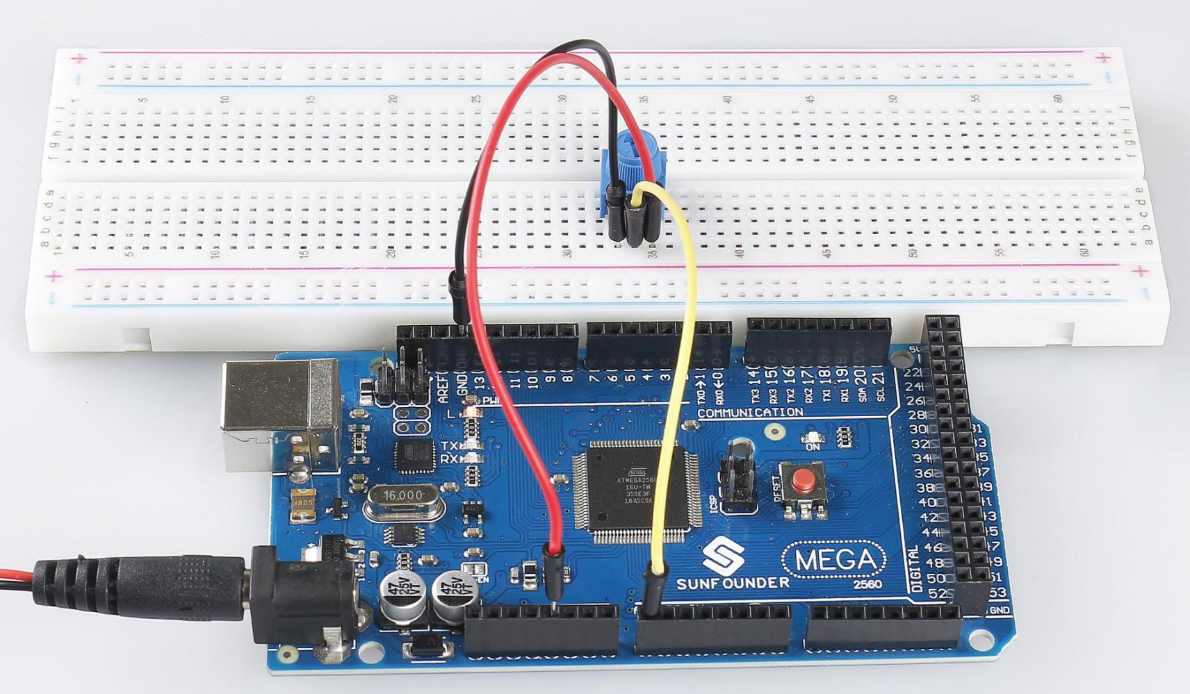
Phenomenon Picture