Note
Hello, welcome to the SunFounder Raspberry Pi & Arduino & ESP32 Enthusiasts Community on Facebook! Dive deeper into Raspberry Pi, Arduino, and ESP32 with fellow enthusiasts.
Why Join?
Expert Support: Solve post-sale issues and technical challenges with help from our community and team.
Learn & Share: Exchange tips and tutorials to enhance your skills.
Exclusive Previews: Get early access to new product announcements and sneak peeks.
Special Discounts: Enjoy exclusive discounts on our newest products.
Festive Promotions and Giveaways: Take part in giveaways and holiday promotions.
👉 Ready to explore and create with us? Click [here] and join today!
1.9 Digital Input Pull-Up
Overview
When using some switch input devices, some pull-up or pull-down resistors are often used to keep the level of corresponding pins at certain value on the condition that the device is not working. Such as in 1.4 Digital Read, a 10k resistor is used to make the pin be connected to GND under the condition that the button is not pressed down. If we have used a lot of switch input components and want to simplify the circuit, we can set the pin mode to「INPUT_PULLUP」in the code so that the pin reads the high level in the suspended state.
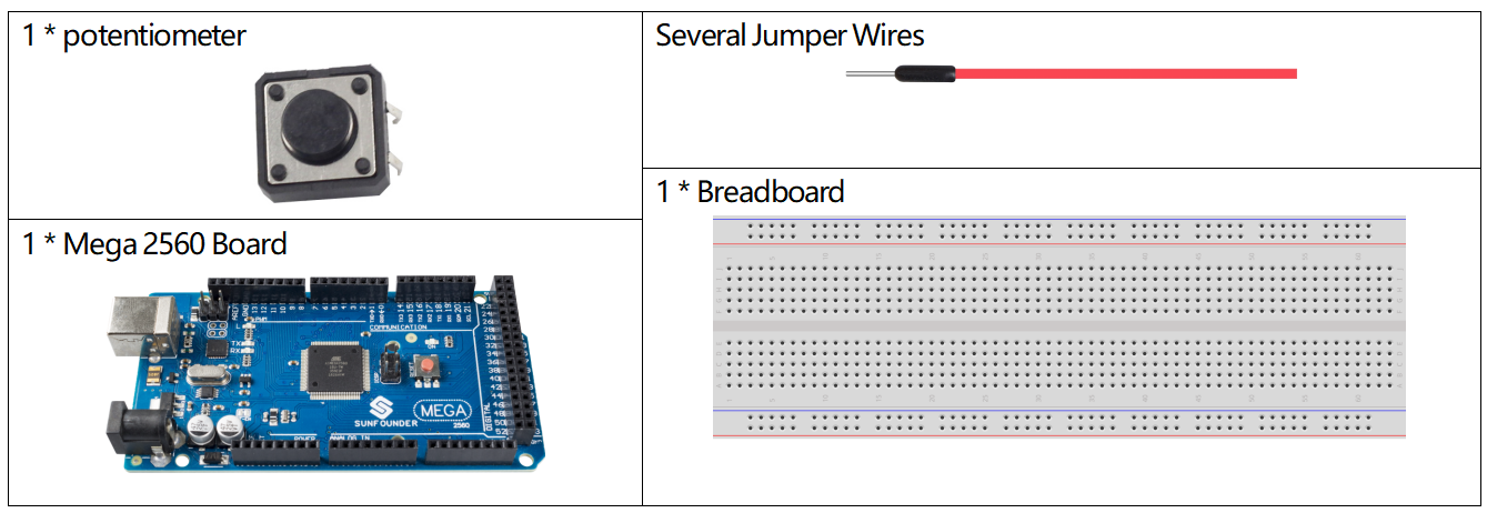
Components Required
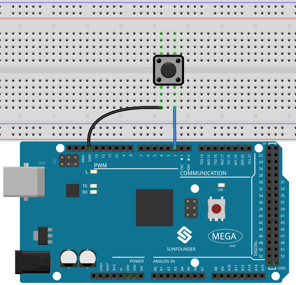
Fritzing Circuit
In this example, we use pin 2 to read the signal of button. The internal pull-up in pin 2 is valid, so if the button isn’t pressed, HIGH is read in pin 2; when the button is pressed, LOW is read.
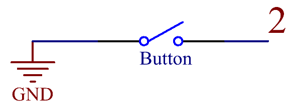
Schematic Diagram
Code
Note
You can open the file
1.9_digitalInputPullup.inounder the path ofsunfounder_vincent_kit_for_arduino\code\1.9_digitalInputPullupdirectly.Or copy this code into Arduino IDE.
After the codes are uploaded to the Mega2560 board, you can open the serial port monitor to view the read values of the pin. When the Button is pressed, the serial port monitor will display “0”, and the “1” will be displayed when the button is released.
Code Analysis
Run the serial communication in setup() and set the data rate to 9600.
Serial.begin(9600);
Configure pin 2 as an input and enable the internal pull-up resistor.
pinMode(2, INPUT_PULLUP);
Read the level state from the digital pin 2 by using digitalRead() statement in loop() and declare a variable to store it.
int buttonState = digitalRead(2);
Print the values stored by variables on the serial port monitor.
Serial.println(buttonState);
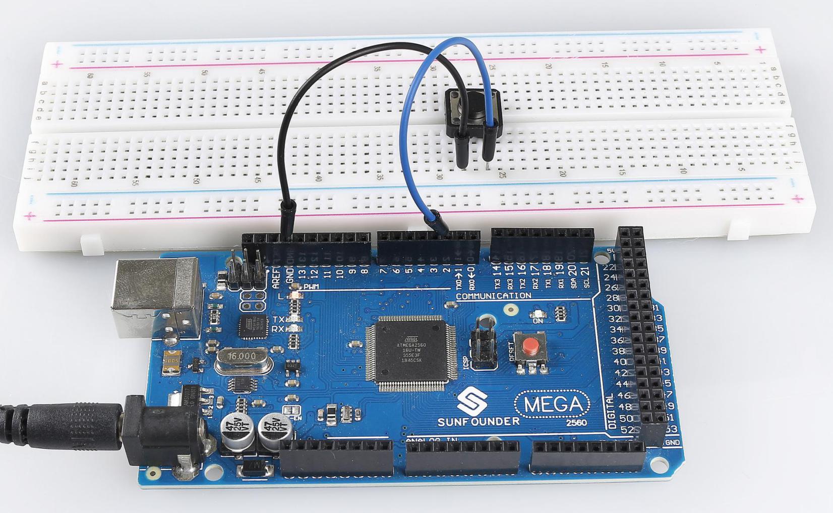
Phenomenon Picture