Note
Hello, welcome to the SunFounder Raspberry Pi & Arduino & ESP32 Enthusiasts Community on Facebook! Dive deeper into Raspberry Pi, Arduino, and ESP32 with fellow enthusiasts.
Why Join?
Expert Support: Solve post-sale issues and technical challenges with help from our community and team.
Learn & Share: Exchange tips and tutorials to enhance your skills.
Exclusive Previews: Get early access to new product announcements and sneak peeks.
Special Discounts: Enjoy exclusive discounts on our newest products.
Festive Promotions and Giveaways: Take part in giveaways and holiday promotions.
👉 Ready to explore and create with us? Click [here] and join today!
2.25 Rotary Encoder Module
Overview
In this lesson, you will learn about Rotary Encoder. A rotary encoder is an electronic switch with a set of regular pulses in strictly timing sequence. When used with IC, it can achieve increment, decrement, page turning and other operations such as mouse scrolling, menu selection, and so on.
Components Required
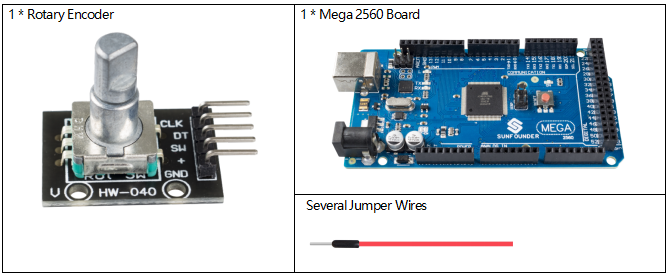
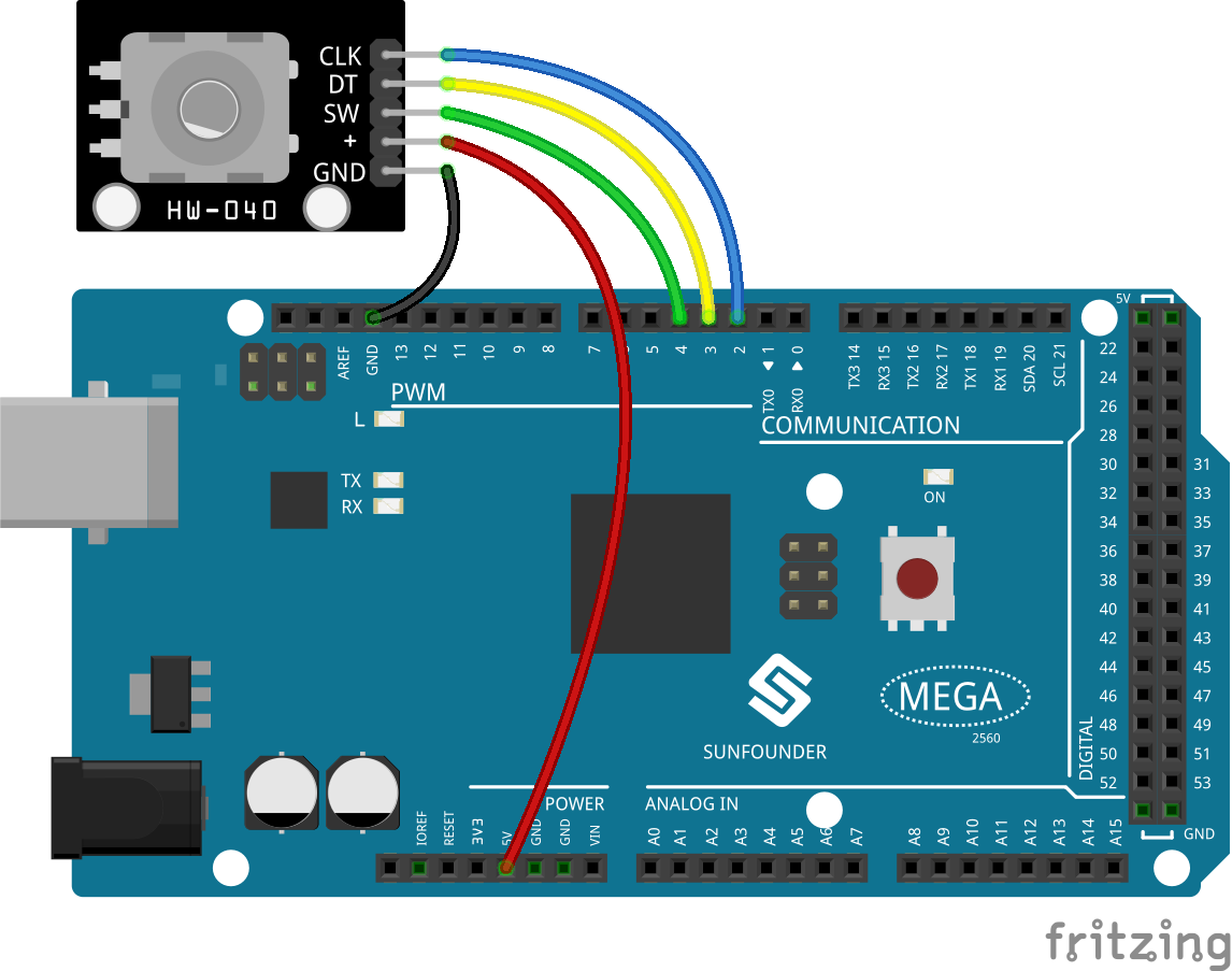
Fritzing Circuit
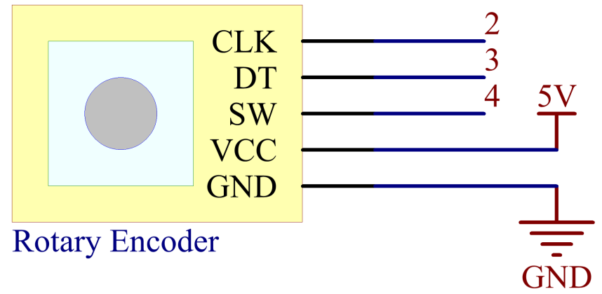
In this example, we can connect the Rotary Encoder pin directly to the Mega 2560 Board pin, connect the GND of the Rotary Encoder to GND, 「+」 to 5V, SW to digital pin 4, DT to digital pin 3, and CLK to digital pin 2.
Schematic Diagram
Code
Note
You can open the file
2.25_rotaryEncoder.inounder the path ofsunfounder_vincent_kit_for_arduino\code\2.25_rotaryEncoderdirectly.Or copy this code into Arduino IDE.
You will see the angular displacement of the rotary encoder printed on Serial Monitor. When you turn the rotary encoder clockwise, the angular displacement is increased; when turn it counterclockwise, the displacement is decreased. If you press the switch on the rotary encoder, the readings will return to zero.
Code Analysis
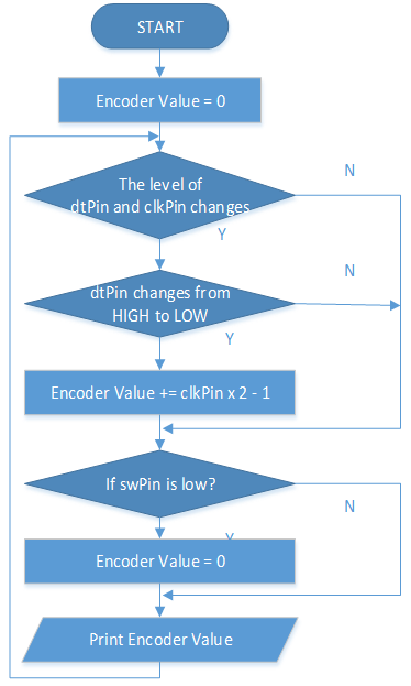
When Rotary Encoder is used, the following situations of pin level will occur.
When rotating the shaft, dtPin will go from high level to low level.
2. clkPin will remain high level when the shaft rotates clockwise, otherwise it goes low level.
When the shaft is pressed, swPin will have low level.
From this, the program flow is shown on the right.
For detailed analysis of potential state change judgment, please refer to 1.10 State Change Detection.
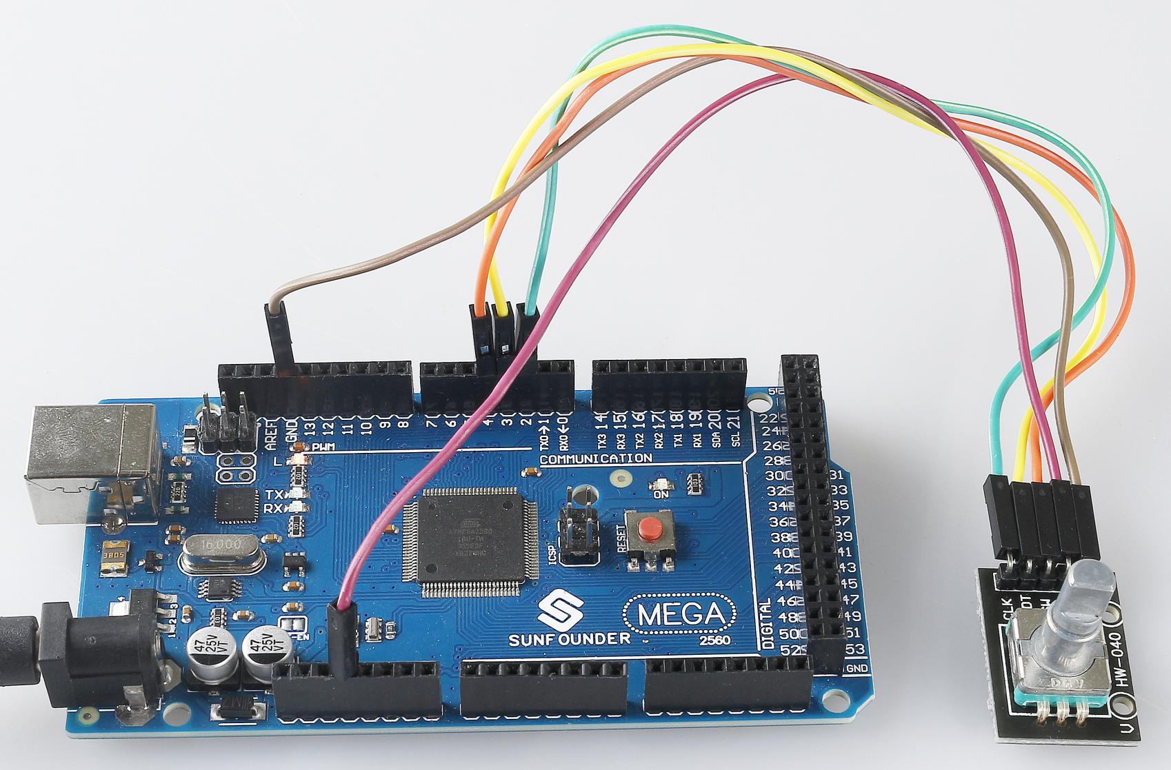
Phenomenon Picture