Nota
¡Hola, bienvenido a la Comunidad de Entusiastas de SunFounder Raspberry Pi & Arduino & ESP32 en Facebook! Sumérgete en el mundo de Raspberry Pi, Arduino y ESP32 junto a otros entusiastas.
¿Por qué unirse?
Soporte experto: Resuelve problemas postventa y desafíos técnicos con la ayuda de nuestra comunidad y equipo.
Aprender y compartir: Intercambia consejos y tutoriales para mejorar tus habilidades.
Preestrenos exclusivos: Obtén acceso anticipado a nuevos anuncios de productos y adelantos.
Descuentos especiales: Disfruta de descuentos exclusivos en nuestros productos más recientes.
Promociones y sorteos festivos: Participa en sorteos y promociones especiales de temporada.
👉 ¿Listo para explorar y crear con nosotros? Haz clic en [Aquí] y únete hoy mismo.
4.1.13 Monitor de Sobrecalentamiento (MCP3008)
Nota
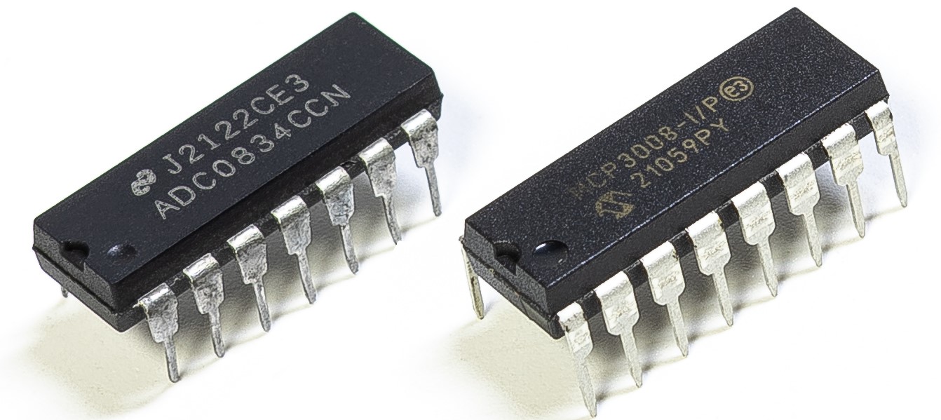
Dependiendo de la versión de tu kit, identifica si tienes ADC0834 o MCP3008 y procede con la sección correspondiente.
Introducción
Puede que desees crear un dispositivo de monitoreo de sobrecalentamiento que se aplique a varias situaciones, por ejemplo, en una fábrica, si queremos tener una alarma y el apagado automático oportuno de la máquina cuando hay un sobrecalentamiento del circuito. En este proyecto, utilizaremos un termistor, un joystick, un zumbador, un LED y una pantalla LCD para hacer un dispositivo inteligente de monitoreo de temperatura cuyo umbral sea ajustable.
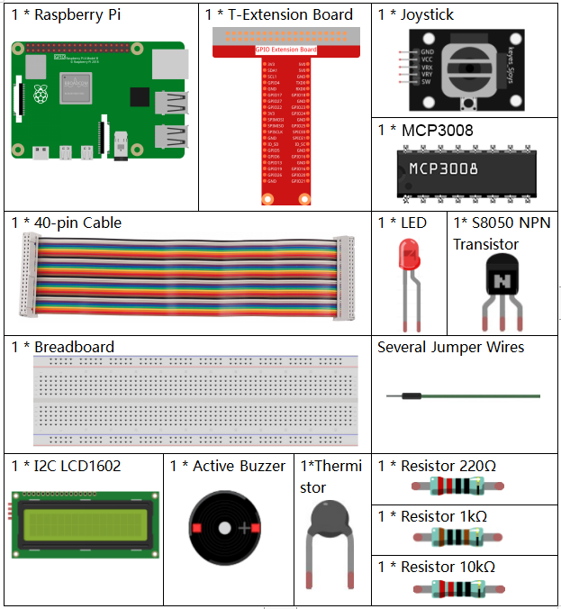
Componentes requeridos
En este proyecto, necesitamos los siguientes componentes.
Es definitivamente conveniente comprar un kit completo, aquí tienes el enlace:
Nombre |
ELEMENTOS EN ESTE KIT |
ENLACE |
|---|---|---|
Kit Raphael |
337 |
También puedes comprarlos por separado en los siguientes enlaces.
INTRODUCCIÓN DEL COMPONENTE |
ENLACE DE COMPRA |
|---|---|
- |
|
- |
|
- |
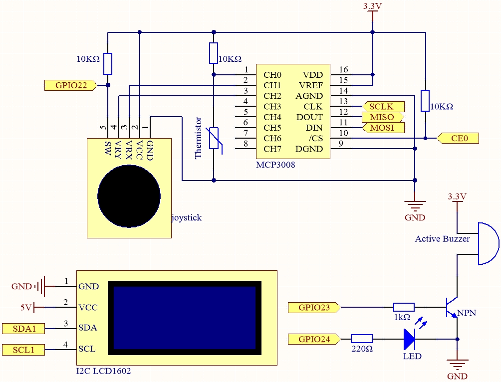
Diagrama esquemático
Nombre |
T-Board |
WiringPi |
BCM |
|---|---|---|---|
SPICE0 |
Pin 24 |
10 |
8 |
SPIMOSI |
Pin 19 |
12 |
10 |
SPIMISO |
Pin 21 |
13 |
9 |
SPISCLK |
Pin 23 |
14 |
11 |
GPIO22 |
Pin 15 |
3 |
22 |
GPIO23 |
Pin 16 |
4 |
23 |
GPIO24 |
Pin 18 |
5 |
24 |
SDA1 |
Pin 3 |
||
SCL1 |
Pin 5 |
Procedimientos experimentales
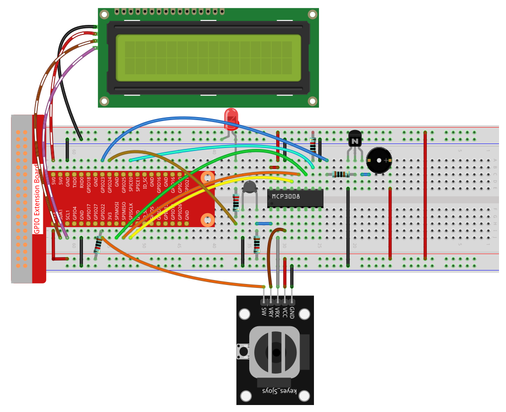
Paso 1: Construye el circuito.
Paso 2: Configura la interfaz SPI e instala la librería spidev (consulta Configuración de SPI para instrucciones detalladas).
Si ya has completado estos pasos, puedes omitirlos.
Paso 3: Ve a la carpeta del código.
cd ~/raphael-kit/python
Paso 4: Ejecuta el archivo.
sudo python3 4.1.13-2_OverheatMonitor.py
Al ejecutar el código, la temperatura actual y el umbral de alta temperatura 40 se muestran en la I2C LCD1602. Si la temperatura actual es mayor que el umbral, el zumbador y el LED se activan para alertarte.
El Joystick se utiliza para ajustar el umbral de alta temperatura. Moviendo el Joystick en la dirección de los ejes X y Y puedes subir o bajar el umbral de temperatura. Presiona el Joystick nuevamente para restablecer el umbral al valor inicial.
Nota
Si obtienes el error
FileNotFoundError: [Errno 2] No such file or directory: '/dev/i2c-1', debes consultar Configuración de I²C para habilitar el I2C.Si obtienes el error
ModuleNotFoundError: No module named 'smbus2', ejecutasudo apt install python3-smbus2.Si aparece el error
OSError: [Errno 121] Remote I/O error, significa que el módulo está mal cableado o defectuoso.Si el código y el cableado son correctos, pero la LCD aún no muestra contenido, ajusta el potenciómetro en la parte trasera para aumentar el contraste.
Advertencia
Si aparece el error RuntimeError: Cannot determine SOC peripheral base address, por favor consulta Si «gpiozero» no funciona.
Código
Nota
Puedes Modificar/Restablecer/Copiar/Ejecutar/Detener el siguiente código.
Pero antes de eso, debes ir a la ruta del código fuente como raphael-kit/python.
Después de modificar el código, puedes ejecutarlo directamente para ver el efecto.
#!/usr/bin/env python3

import RPi.GPIO as GPIO
import spidev
import time
import math
import LCD1602

# Definiciones de pines GPIO
JOY_BTN_PIN = 22  # Botón
BUZZER_PIN = 23   # Zumbador
LED_PIN = 24      # LED

# Inicialización de GPIO
GPIO.setmode(GPIO.BCM)
GPIO.setup(JOY_BTN_PIN, GPIO.IN, pull_up_down=GPIO.PUD_UP)
GPIO.setup(BUZZER_PIN, GPIO.OUT)
GPIO.setup(LED_PIN, GPIO.OUT)

# Umbral inicial de temperatura
upperTem = 40

# Inicializar SPI para MCP3008
spi = spidev.SpiDev()
spi.open(0, 0)
spi.max_speed_hz = 1000000  # 1 MHz

# Inicializar LCD1602
LCD1602.init(0x27, 1)

def read_adc(channel):
    if channel < 0 or channel > 7:
        return -1
    adc = spi.xfer2([1, (8 + channel) << 4, 0])
    value = ((adc[1] & 0x03) << 8) | adc[2]
    return value

def get_joystick_value():
    x_val = read_adc(1)
    y_val = read_adc(2)
    if x_val > 800:
        return 1
    elif x_val < 200:
        return -1
    elif y_val > 800:
        return -10
    elif y_val < 200:
        return 10
    else:
        return 0

def upper_tem_setting():
    global upperTem
    LCD1602.write(0, 0, 'Upper Adjust: ')
    change = int(get_joystick_value())
    upperTem += change
    strUpperTem = str(upperTem)
    LCD1602.write(0, 1, strUpperTem)
    LCD1602.write(len(strUpperTem), 1, '              ')
    time.sleep(0.1)

def temperature():
    analogVal = read_adc(0)
    Vr = 3.3 * analogVal / 1023.0
    if Vr == 0:
        return 0
    Rt = 10000.0 * (3.3 - Vr) / Vr
    tempK = 1.0 / (((math.log(Rt / 10000.0)) / 3950.0) + (1.0 / (273.15 + 25.0)))
    Cel = tempK - 273.15
    return round(Cel, 2)

def monitoring_temp():
    global upperTem
    Cel = temperature()
    LCD1602.write(0, 0, 'Temp: ')
    LCD1602.write(0, 1, 'Upper: ')
    LCD1602.write(6, 0, str(Cel))
    LCD1602.write(7, 1, str(upperTem))
    time.sleep(0.1)
    if Cel >= upperTem:
        GPIO.output(BUZZER_PIN, GPIO.HIGH)
        GPIO.output(LED_PIN, GPIO.HIGH)
    else:
        GPIO.output(BUZZER_PIN, GPIO.LOW)
        GPIO.output(LED_PIN, GPIO.LOW)

try:
    lastState = GPIO.input(JOY_BTN_PIN)
    stage = 0
    while True:
        currentState = GPIO.input(JOY_BTN_PIN)
        if currentState == GPIO.HIGH and lastState == GPIO.LOW:
            stage = (stage + 1) % 2
            time.sleep(0.1)
            LCD1602.clear()
        lastState = currentState

        if stage == 1:
            upper_tem_setting()
        else:
            monitoring_temp()

except KeyboardInterrupt:
    pass

finally:
    LCD1602.clear()
    GPIO.cleanup()
    spi.close()
Explicación del código
Importación de librerías
Carga las librerías necesarias para controlar GPIO, SPI, LCD, retrasos y cálculos matemáticos.
#!/usr/bin/env python3
import RPi.GPIO as GPIO
import spidev
import time
import math
import LCD1602
Configuración de pines GPIO
Define los pines GPIO para el botón del joystick, zumbador y LED.
JOY_BTN_PIN = 22  # Button pin
BUZZER_PIN = 23   # Buzzer pin
LED_PIN = 24      # LED pin

GPIO.setmode(GPIO.BCM)
GPIO.setup(JOY_BTN_PIN, GPIO.IN, pull_up_down=GPIO.PUD_UP)
GPIO.setup(BUZZER_PIN, GPIO.OUT)
GPIO.setup(LED_PIN, GPIO.OUT)
Inicialización de SPI y LCD
Abre la interfaz SPI para MCP3008 y configura la pantalla LCD1602 en la dirección I2C 0x27.
upperTem = 40
spi = spidev.SpiDev()
spi.open(0, 0)
spi.max_speed_hz = 1000000

LCD1602.init(0x27, 1)
Lectura ADC
Lee valores analógicos de los canales 0–7 del MCP3008.
def read_adc(channel):
    if channel < 0 or channel > 7:
        return -1
    adc = spi.xfer2([1, (8 + channel) << 4, 0])
    value = ((adc[1] & 0x03) << 8) | adc[2]
    return value
Lectura del Joystick
Interpreta la posición del joystick para modificar el umbral.
def get_joystick_value():
    x_val = read_adc(1)
    y_val = read_adc(2)
    if x_val > 800:
        return 1
    elif x_val < 200:
        return -1
    elif y_val > 800:
        return -10
    elif y_val < 200:
        return 10
    else:
        return 0
Ajuste del umbral
Muestra “Upper Adjust” en la pantalla y ajusta el umbral según el joystick.
def upper_tem_setting():
    global upperTem
    LCD1602.write(0, 0, 'Upper Adjust: ')
    change = int(get_joystick_value())
    upperTem += change
    strUpperTem = str(upperTem)
    LCD1602.write(0, 1, strUpperTem)
    LCD1602.write(len(strUpperTem), 1, '              ')
    time.sleep(0.1)
Cálculo de temperatura
Convierte el valor analógico del sensor en temperatura (°C) usando la ecuación Steinhart–Hart.
def temperature():
    analogVal = read_adc(0)
    Vr = 3.3 * analogVal / 1023.0
    if Vr == 0:
        return 0
    Rt = 10000.0 * (3.3 - Vr) / Vr
    tempK = 1.0 / (((math.log(Rt / 10000.0)) / 3950.0) + (1.0 / (273.15 + 25.0)))
    Cel = tempK - 273.15
    return round(Cel, 2)
Monitoreo de temperatura
Muestra la temperatura y el umbral en la pantalla, activa el zumbador y el LED si se supera el umbral.
def monitoring_temp():
    global upperTem
    Cel = temperature()
    LCD1602.write(0, 0, 'Temp: ')
    LCD1602.write(0, 1, 'Upper: ')
    LCD1602.write(6, 0, str(Cel))
    LCD1602.write(7, 1, str(upperTem))
    time.sleep(0.1)
    if Cel >= upperTem:
        GPIO.output(BUZZER_PIN, GPIO.HIGH)
        GPIO.output(LED_PIN, GPIO.HIGH)
    else:
        GPIO.output(BUZZER_PIN, GPIO.LOW)
        GPIO.output(LED_PIN, GPIO.LOW)
Lógica principal
Cambia entre modo de ajuste de umbral y monitoreo al presionar el botón del joystick.
try:
    lastState = GPIO.input(JOY_BTN_PIN)
    stage = 0
    while True:
        currentState = GPIO.input(JOY_BTN_PIN)
        if currentState == GPIO.HIGH and lastState == GPIO.LOW:
            stage = (stage + 1) % 2
            time.sleep(0.1)
            LCD1602.clear()
        lastState = currentState

        if stage == 1:
            upper_tem_setting()
        else:
            monitoring_temp()
Limpieza al salir
Apaga el zumbador, limpia GPIO y cierra la interfaz SPI.
except KeyboardInterrupt:
    pass
finally:
    LCD1602.clear()
    GPIO.cleanup()
    spi.close()