Nota
Ciao, benvenuto nella Community Facebook di appassionati di SunFounder Raspberry Pi & Arduino & ESP32! Approfondisci Raspberry Pi, Arduino ed ESP32 con altri appassionati.
Perché unirsi?
Supporto esperto: Risolvi problemi post-vendita e sfide tecniche con l’aiuto della nostra community e del nostro team.
Impara e condividi: Scambia suggerimenti e tutorial per migliorare le tue competenze.
Anteprime esclusive: Ottieni l’accesso anticipato agli annunci di nuovi prodotti e alle anteprime.
Sconti speciali: Goditi sconti esclusivi sui nostri prodotti più recenti.
Promozioni festive e giveaway: Partecipa a giveaway e promozioni festive.
👉 Pronto a esplorare e creare con noi? Clicca [Qui] e unisciti oggi stesso!
4.1.13 Monitor di Surriscaldamento (MCP3008)
Nota
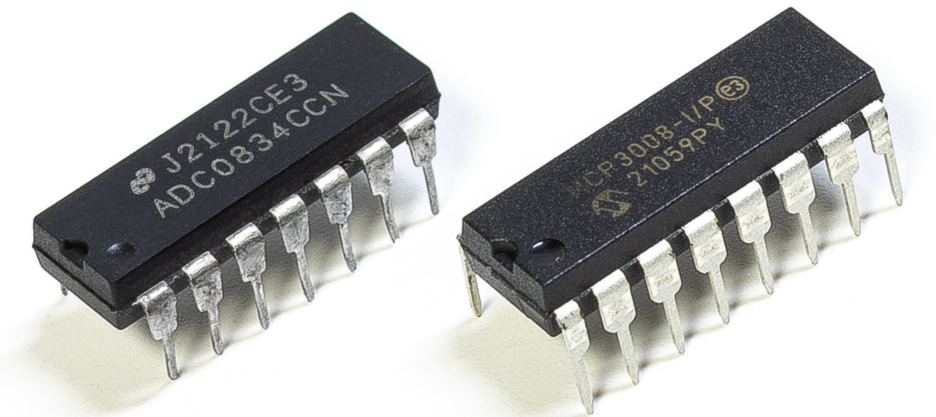
A seconda della versione del tuo kit, identifica se hai ADC0834 o MCP3008 e procedi con la sezione corrispondente.
Introduzione
Potresti voler realizzare un dispositivo di monitoraggio del surriscaldamento applicabile a varie situazioni, ad esempio in fabbrica, per attivare un allarme e spegnere automaticamente la macchina quando si verifica un surriscaldamento di un circuito. In questo progetto useremo termistore, joystick, buzzer, LED e LCD per realizzare un dispositivo intelligente di monitoraggio della temperatura con soglia regolabile.
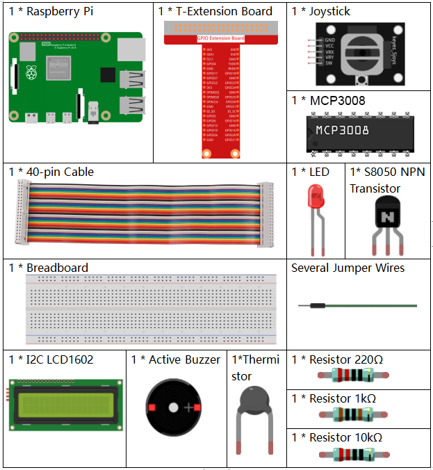
Componenti richiesti
In questo progetto, abbiamo bisogno dei seguenti componenti.
È sicuramente conveniente acquistare un kit completo, ecco il link:
Nome |
ARTICOLI IN QUESTO KIT |
LINK |
|---|---|---|
Raphael Kit |
337 |
Puoi anche acquistarli separatamente dai link sottostanti.
INTRODUZIONE COMPONENTE |
LINK DI ACQUISTO |
|---|---|
- |
|
- |
|
- |
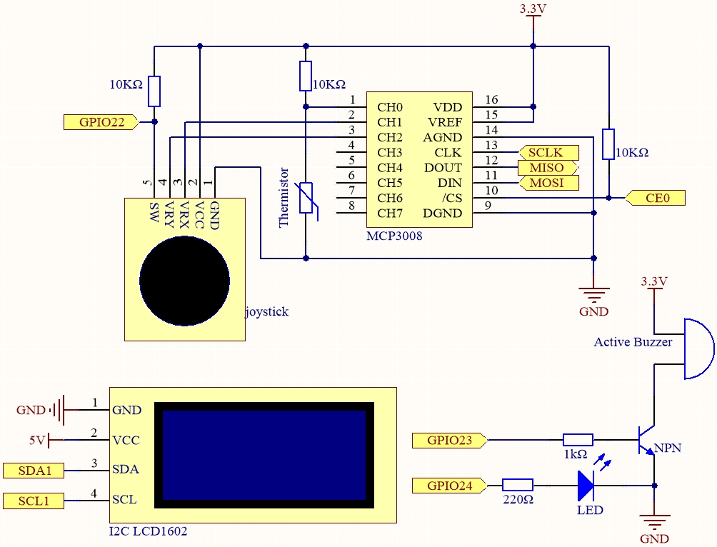
Schema elettrico
Nome T-Board |
fisico |
wiringPi |
BCM |
SPICE0 |
Pin 24 |
10 |
8 |
SPIMOSI |
Pin 19 |
12 |
10 |
SPIMISO |
Pin 21 |
13 |
9 |
SPISCLK |
Pin 23 |
14 |
11 |
GPIO22 |
Pin 15 |
3 |
22 |
GPIO23 |
Pin 16 |
4 |
23 |
GPIO24 |
Pin 18 |
5 |
24 |
SDA1 |
Pin 3 |
||
SCL1 |
Pin 5 |
Procedure sperimentali
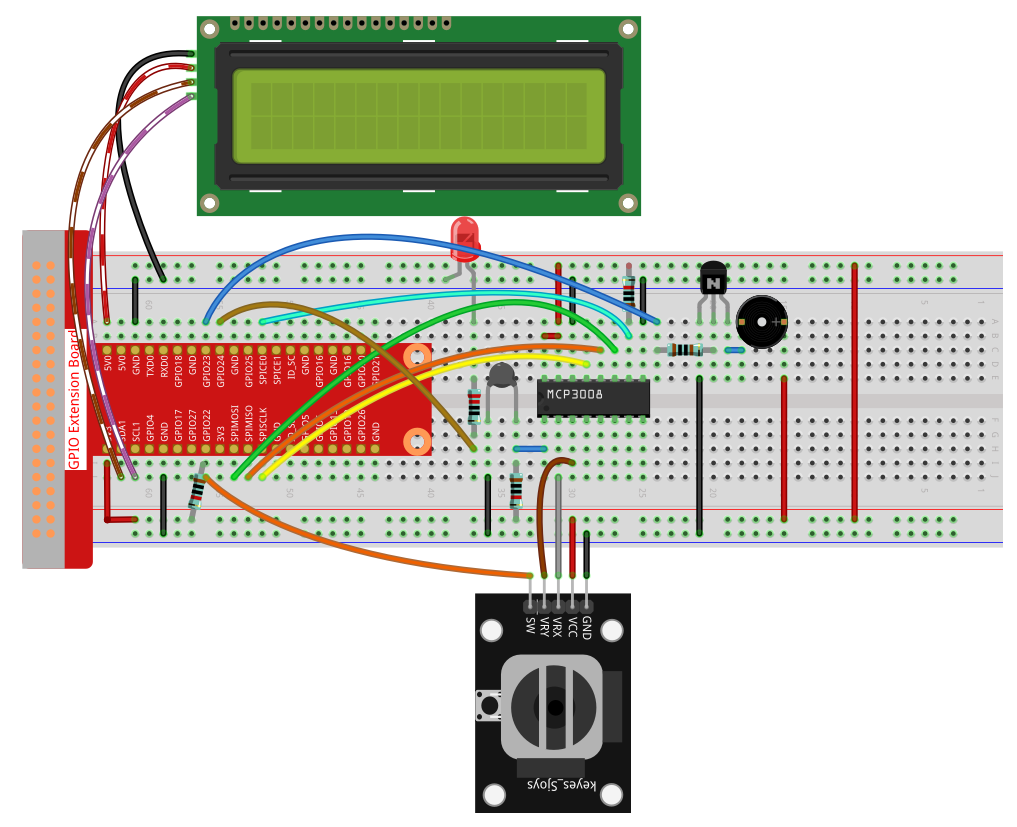
Passo 1: Costruisci il circuito.
Passo 2: Configura l’interfaccia SPI e installa la libreria spidev (vedi Configurazione SPI per istruzioni dettagliate).
Se hai già completato questi passaggi, puoi saltarli.
Passo 3: Vai nella cartella del codice.
cd ~/raphael-kit/python
Passo 4: Esegui il file eseguibile.
sudo python3 4.1.13-2_OverheatMonitor.py
Quando il codice è in esecuzione, la temperatura attuale e la soglia di alta temperatura 40 vengono visualizzate su I2C LCD1602. Se la temperatura corrente è superiore alla soglia, il buzzer e il LED vengono attivati per avvisarti.
Il Joystick serve per regolare la soglia di temperatura elevata. Spostando il Joystick lungo l’asse X e Y è possibile aumentare o diminuire la soglia corrente. Premendo nuovamente il Joystick si ripristina la soglia al valore iniziale.
Nota
Se ricevi l’errore
FileNotFoundError: [Errno 2] No such file or directory: '/dev/i2c-1', fai riferimento a Configurazione I²C per abilitare l’I2C.Se ricevi l’errore
ModuleNotFoundError: No module named 'smbus2', eseguisudo apt install python3-smbus2.Se appare l’errore
OSError: [Errno 121] Remote I/O error, significa che il modulo è collegato male o guasto.Se il codice e i collegamenti sono corretti ma l’LCD non mostra contenuti, ruota il potenziometro sul retro per aumentare il contrasto.
Avvertimento
Se compare il messaggio di errore RuntimeError: Cannot determine SOC peripheral base address, fai riferimento a If gpiozero doesn’t work.
Codice
Nota
Puoi Modificare/Resettare/Copiare/Eseguire/Fermare il codice qui sotto.
Prima però devi andare nel percorso del codice sorgente come raphael-kit/python.
Dopo aver modificato il codice, puoi eseguirlo direttamente per vedere l’effetto.
#!/usr/bin/env python3

import RPi.GPIO as GPIO
import spidev
import time
import math
import LCD1602

# Pin GPIO
JOY_BTN_PIN = 22  # Pulsante joystick
BUZZER_PIN = 23   # Pin buzzer
LED_PIN = 24      # Pin LED

GPIO.setmode(GPIO.BCM)
GPIO.setup(JOY_BTN_PIN, GPIO.IN, pull_up_down=GPIO.PUD_UP)
GPIO.setup(BUZZER_PIN, GPIO.OUT)
GPIO.setup(LED_PIN, GPIO.OUT)

upperTem = 40

spi = spidev.SpiDev()
spi.open(0, 0)
spi.max_speed_hz = 1000000  # 1 MHz

LCD1602.init(0x27, 1)

def read_adc(channel):
    if channel < 0 or channel > 7:
        return -1
    adc = spi.xfer2([1, (8 + channel) << 4, 0])
    value = ((adc[1] & 0x03) << 8) | adc[2]
    return value

def get_joystick_value():
    x_val = read_adc(1)
    y_val = read_adc(2)
    if x_val > 800:
        return 1
    elif x_val < 200:
        return -1
    elif y_val > 800:
        return -10
    elif y_val < 200:
        return 10
    else:
        return 0

def upper_tem_setting():
    global upperTem
    LCD1602.write(0, 0, 'Upper Adjust: ')
    change = int(get_joystick_value())
    upperTem += change
    strUpperTem = str(upperTem)
    LCD1602.write(0, 1, strUpperTem)
    LCD1602.write(len(strUpperTem), 1, '              ')
    time.sleep(0.1)

def temperature():
    analogVal = read_adc(0)
    Vr = 3.3 * analogVal / 1023.0
    if Vr == 0:
        return 0
    Rt = 10000.0 * (3.3 - Vr) / Vr
    tempK = 1.0 / (((math.log(Rt / 10000.0)) / 3950.0) + (1.0 / (273.15 + 25.0)))
    Cel = tempK - 273.15
    return round(Cel, 2)

def monitoring_temp():
    global upperTem
    Cel = temperature()
    LCD1602.write(0, 0, 'Temp: ')
    LCD1602.write(0, 1, 'Upper: ')
    LCD1602.write(6, 0, str(Cel))
    LCD1602.write(7, 1, str(upperTem))
    time.sleep(0.1)
    if Cel >= upperTem:
        GPIO.output(BUZZER_PIN, GPIO.HIGH)
        GPIO.output(LED_PIN, GPIO.HIGH)
    else:
        GPIO.output(BUZZER_PIN, GPIO.LOW)
        GPIO.output(LED_PIN, GPIO.LOW)

try:
    lastState = GPIO.input(JOY_BTN_PIN)
    stage = 0
    while True:
        currentState = GPIO.input(JOY_BTN_PIN)
        if currentState == GPIO.HIGH and lastState == GPIO.LOW:
            stage = (stage + 1) % 2
            time.sleep(0.1)
            LCD1602.clear()
        lastState = currentState

        if stage == 1:
            upper_tem_setting()
        else:
            monitoring_temp()

except KeyboardInterrupt:
    pass

finally:
    LCD1602.clear()
    GPIO.cleanup()
    spi.close()
Spiegazione del codice
Importazione librerie
Carica le librerie richieste per GPIO, SPI, LCD, gestione del tempo e operazioni matematiche.
#!/usr/bin/env python3
import RPi.GPIO as GPIO
import spidev
import time
import math
import LCD1602
Configurazione GPIO e dispositivi
Definisce i pin per joystick, buzzer e LED e imposta la modalità GPIO.
JOY_BTN_PIN = 22  # Button pin
BUZZER_PIN = 23   # Buzzer pin
LED_PIN = 24      # LED pin

GPIO.setmode(GPIO.BCM)
GPIO.setup(JOY_BTN_PIN, GPIO.IN, pull_up_down=GPIO.PUD_UP)
GPIO.setup(BUZZER_PIN, GPIO.OUT)
GPIO.setup(LED_PIN, GPIO.OUT)
Inizializzazione SPI e LCD
Avvia l’interfaccia SPI per MCP3008 e inizializza l’LCD1602 con indirizzo I2C 0x27.
upperTem = 40
spi = spidev.SpiDev()
spi.open(0, 0)
spi.max_speed_hz = 1000000

LCD1602.init(0x27, 1)
Funzione lettura ADC
Legge valori analogici da MCP3008 (0–7).
def read_adc(channel):
    if channel < 0 or channel > 7:
        return -1
    adc = spi.xfer2([1, (8 + channel) << 4, 0])
    value = ((adc[1] & 0x03) << 8) | adc[2]
    return value
Rilevamento movimento joystick
Controlla gli assi X/Y del joystick e restituisce un valore per modificare la soglia.
def get_joystick_value():
    x_val = read_adc(1)
    y_val = read_adc(2)
    if x_val > 800:
        return 1
    elif x_val < 200:
        return -1
    elif y_val > 800:
        return -10
    elif y_val < 200:
        return 10
    else:
        return 0
Impostazione soglia
Mostra “Upper Adjust” su LCD e aggiorna la soglia in base al joystick.
def upper_tem_setting():
    global upperTem
    LCD1602.write(0, 0, 'Upper Adjust: ')
    change = int(get_joystick_value())
    upperTem += change
    strUpperTem = str(upperTem)
    LCD1602.write(0, 1, strUpperTem)
    LCD1602.write(len(strUpperTem), 1, '              ')
    time.sleep(0.1)
Calcolo temperatura
Converte la lettura analogica in tensione, resistenza e poi temperatura (°C) con l’equazione Steinhart–Hart.
def temperature():
    analogVal = read_adc(0)
    Vr = 3.3 * analogVal / 1023.0
    if Vr == 0:
        return 0
    Rt = 10000.0 * (3.3 - Vr) / Vr
    tempK = 1.0 / (((math.log(Rt / 10000.0)) / 3950.0) + (1.0 / (273.15 + 25.0)))
    Cel = tempK - 273.15
    return round(Cel, 2)
Monitoraggio temperatura
Visualizza temperatura e soglia; attiva buzzer e LED se si supera la soglia.
def monitoring_temp():
    global upperTem
    Cel = temperature()
    LCD1602.write(0, 0, 'Temp: ')
    LCD1602.write(0, 1, 'Upper: ')
    LCD1602.write(6, 0, str(Cel))
    LCD1602.write(7, 1, str(upperTem))
    time.sleep(0.1)
    if Cel >= upperTem:
        GPIO.output(BUZZER_PIN, GPIO.HIGH)
        GPIO.output(LED_PIN, GPIO.HIGH)
    else:
        GPIO.output(BUZZER_PIN, GPIO.LOW)
        GPIO.output(LED_PIN, GPIO.LOW)
Logica principale
Alterna tra modalità monitoraggio e modalità impostazione soglia premendo il joystick.
try:
    lastState = GPIO.input(JOY_BTN_PIN)
    stage = 0
    while True:
        currentState = GPIO.input(JOY_BTN_PIN)
        if currentState == GPIO.HIGH and lastState == GPIO.LOW:
            stage = (stage + 1) % 2
            time.sleep(0.1)
            LCD1602.clear()
        lastState = currentState

        if stage == 1:
            upper_tem_setting()
        else:
            monitoring_temp()
Pulizia in uscita
Spegne correttamente GPIO, LCD e SPI alla chiusura del programma.
except KeyboardInterrupt:
    pass
finally:
    LCD1602.clear()
    GPIO.cleanup()
    spi.close()