注釈
こんにちは、SunFounderのRaspberry Pi & Arduino & ESP32愛好家コミュニティへようこそ!Facebook上でRaspberry Pi、Arduino、ESP32についてもっと深く掘り下げ、他の愛好家と交流しましょう。
参加する理由は?
エキスパートサポート:コミュニティやチームの助けを借りて、販売後の問題や技術的な課題を解決します。
学び&共有:ヒントやチュートリアルを交換してスキルを向上させましょう。
独占的なプレビュー:新製品の発表や先行プレビューに早期アクセスしましょう。
特別割引:最新製品の独占割引をお楽しみください。
祭りのプロモーションとギフト:ギフトや祝日のプロモーションに参加しましょう。
👉 私たちと一緒に探索し、創造する準備はできていますか?[ここ]をクリックして今すぐ参加しましょう!
7.12 デジタル水平器
水平器 は、面が水平(レベル)か垂直(垂直)かを示すための計測器具です。大工、石工、レンガ職人、他の建築関連の作業者、測量士、精密機械工、そして一部の写真やビデオ作業にも使用されるさまざまな種類の水平器があります。
ここでは、MPU6050と8x8 LEDマトリックスを使用してデジタル水平器を作成します。MPU6050を傾けると、LEDマトリックス上のバブルも傾きます。
必要なコンポーネント
このプロジェクトで必要なコンポーネントは以下の通りです。
一式をまとめて購入する方が便利です。リンクはこちら:
名前 |
このキットに含まれるアイテム |
リンク |
|---|---|---|
ケプラーキット |
450+ |
以下のリンクから個別にも購入できます。
SN |
コンポーネント |
数量 |
リンク |
|---|---|---|---|
1 |
1 |
||
2 |
Micro USBケーブル |
1 |
|
3 |
1 |
||
4 |
いくつか |
||
5 |
1 |
||
6 |
2 |
||
7 |
1 |
回路図
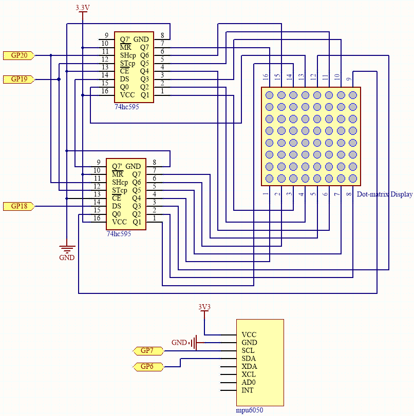
MPU6050は、各方向の加速度値を取得し、姿勢角を計算します。 その結果、プログラムは、2つの74HC595チップからのデータに基づいて、ドットマトリックス上に2x2のドットを描画します。 姿勢角が変わると、プログラムは74HC595チップに異なるデータを送信し、ドットの位置が変わり、バブル効果が生まれます。
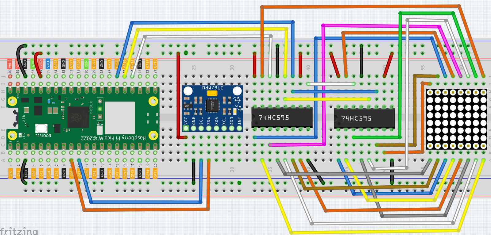
配線
コード
注釈
kepler-kit-main/micropythonフォルダの7.12_digital_bubble_level.pyファイルを開いて実行するか、このコードをThonnyにコピーして「Run Current Script」をクリック、またはF5キーを押して実行してください。右下の角にある「MicroPython(Raspberry Pi Pico)」のインタープリターを選択することを忘れないでください。
詳細なチュートリアルは、 コードを直接開いて実行する を参照してください。
ここでは
imu.pyとvector3d.pyが必要です。Pico Wにアップロードされているかどうか確認してください。詳細なチュートリアルは 1.4 Picoにライブラリをアップロード を参照してください。
import machine
from machine import I2C, Pin
import time
import math
from imu import MPU6050

# Initialize I2C communication with MPU6050 sensor
i2c = I2C(1, sda=Pin(6), scl=Pin(7), freq=400000)
mpu = MPU6050(i2c)

# Function to calculate the distance between two points
def dist(a, b):
    return math.sqrt((a * a) + (b * b))

# Function to calculate rotation along the y-axis
def get_y_rotation(x, y, z):
    radians = math.atan2(x, dist(y, z))
    return -math.degrees(radians)

# Function to calculate rotation along the x-axis
def get_x_rotation(x, y, z):
    radians = math.atan2(y, dist(x, z))
    return math.degrees(radians)

# Function to get the current angles from the MPU6050 sensor
def get_angle():
    y_angle = get_y_rotation(mpu.accel.x, mpu.accel.y, mpu.accel.z)
    x_angle = get_x_rotation(mpu.accel.x, mpu.accel.y, mpu.accel.z)
    return x_angle, y_angle

# Initialize shift register pins for controlling the LED matrix
sdi = machine.Pin(18, machine.Pin.OUT)
rclk = machine.Pin(19, machine.Pin.OUT)
srclk = machine.Pin(20, machine.Pin.OUT)

# Function to shift data into the shift register
def hc595_in(dat):
    for bit in range(7, -1, -1):
        srclk.low()
        time.sleep_us(30)
        sdi.value(1 & (dat >> bit))
        time.sleep_us(30)
        srclk.high()

# Function to output the data from the shift register to the LED matrix
def hc595_out():
    rclk.high()
    time.sleep_us(200)
    rclk.low()

# Function to display a glyph (8x8 matrix) on the LED matrix
def display(glyph):
    for i in range(0, 8):
        hc595_in(glyph[i])
        hc595_in(0x80 >> i)
        hc595_out()

# Convert a 2D matrix to a glyph that can be displayed on the LED matrix
def matrix_2_glyph(matrix):
    glyph = [0 for i in range(8)]
    for i in range(8):
        for j in range(8):
            glyph[i] += matrix[i][j] << j
    return glyph

# Clamp a value between a specified minimum and maximum
def clamp_number(val, min_val, max_val):
    return min_val if val < min_val else max_val if val > max_val else val

# Map a value from one range to another
def interval_mapping(x, in_min, in_max, out_min, out_max):
    return (x - in_min) * (out_max - out_min) / (in_max - in_min) + out_min

# Calculate the position of the bubble in the matrix based on the MPU6050 readings
sensitivity = 4  # Sensitivity of the bubble movement
matrix_range = 7  # The matrix size is 8x8, so the range is 0-7
point_range = matrix_range - 1  # Bubble's position should be between 0 and 6

# Function to calculate the position of the bubble based on sensor data
def bubble_position():
    y, x = get_angle()  # Get the current rotation angles
    x = int(clamp_number(interval_mapping(x, 90, -90, 0 - sensitivity, point_range + sensitivity), 0, point_range))
    y = int(clamp_number(interval_mapping(y, -90, 90, point_range + sensitivity, 0 - sensitivity), 0, point_range))
    return [x, y]

# Drop the bubble (represented by turning off 2x2 LEDs) into the matrix
def drop_bubble(matrix, bubble):
    matrix[bubble[0]][bubble[1]] = 0
    matrix[bubble[0] + 1][bubble[1]] = 0
    matrix[bubble[0]][bubble[1] + 1] = 0
    matrix[bubble[0] + 1][bubble[1] + 1] = 0
    return matrix

# Main loop
while True:
    matrix = [[1 for i in range(8)] for j in range(8)]  # Create an empty matrix (all LEDs on)
    bubble = bubble_position()  # Get the current bubble position based on sensor data
    matrix = drop_bubble(matrix, bubble)  # Drop the bubble into the matrix
    display(matrix_2_glyph(matrix))  # Display the matrix on the LED grid
    time.sleep(0.1)  # Add a small delay to slow down updates
プログラムを実行した後、ブレッドボードを水平な面に置いてください。 LEDマトリックスの中央にドットが表示されます(中央にない場合は、MPU6050が水平でない可能性があります)。 ブレッドボードを傾けると、ドットも傾けた方向に動きます。